
Service manual


STP 11-25R13-SM-TG
R - 1
APPENDIX R – RELAY GUIDELINES
R-1. Problems with Relays.
a. The moving armature in a relay can cause malfunctions due to the fact that any moving part will
eventually wear out. Also remember that the armature is attracted by a coil's magnetic field; if the coil
burns out there will be no field to move the armature. The spring, the restoring force, can break or lose
its tension, causing the armature to stay in its energized position even if the current flow through the coil
is turned off.
b. One more problem with relays is the switching contacts. Every time a pair of contacts moves
apart, a little spark occurs. The same thing happens every time two contacts come together. This
sparking eventually causes the contacts to burn, resulting in a poor connection that interrupts the path for
current in the controlled circuit.
c. If a relay is believed to be the cause of a circuit not working properly, check the relay with a
multimeter. Check voltage with the power on. Check resistance with the power removed.
R-2. Voltage Checks.
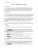
a. In many pieces of military equipment, the relay coil is connected to a 28 VDC source, as shown
in Figure R-1. When the switch is closed, the path for current is complete and current should flow
through the coil. To ensure that the switch and the connecting wires are good, a voltmeter can be
connected to the coil connections (3 and 7). If 28V are indicated, the primary power is getting to the
relay.
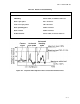
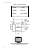
Figure R-1. Relay Checks
b. Even if the coil is getting its voltage, the relay may still malfunction. In Figure R-1, 115 VAC is
present at the lower wiper (contact 6).
(1) If the relay energizes properly, 115 VAC should also be present at contact 1. If a voltmeter
indicates that 115 VAC is not present at contact 1, then either the armature is not moving or there is a
poor connection between switching contacts.
(2) Since the relay is supposed to be energized, the voltage at deenergized contact 8 should read
zero volts on a voltmeter. A 115 VAC reading would indicate that the relay is not energizing correctly.
c. The upper wiper, contact 2, has 25 VAC applied to it. If the relay is supposed to be energized,
then the same 25 VAC should also be present at contact 5. A voltmeter connected to contact 5 should
indicate 25 VAC. There should be zero volts at contact 4. If the voltmeter indicates zero volts at contact
5 and 25 VAC at contact 4, the relay is not energizing.
d. If the relay were deenergized (the switch would be off), a voltmeter would be expected to
indicate 115 VAC at contacts 6 and 8, but zero volts at contact 1. Twenty-five volts AC would be