
Service manual


STP 11-25R13-SM-TG
Q - 38
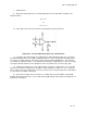
(6) The input resistance (R
i
) is the resistance looking into the two inputs as seen in Figure Q-34.
Ideally this value is 00; however in practice, the value ranges from about 5k to more than 20M. This
value is measured in the open loop hookup and can be increased by adding feedback so that op amps
can be used with high resistance signal sources.
Figure Q-34. Input Resistance
(7) Output resistance (R
O
) is ideally 0, meaning that all of the generated output voltage is sent
across the lead circuit. In the open loop configuration, R
O
equals a few ohms to a few hundred ohms.
Again, with feedback, this value can be reduced to almost the ideal 0 value.
(8) One of the characteristics that must be observed very closely is the power requirement. Most
op amps require both a positive and negative supply and these supplies must be well filtered and
regulated.
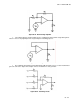
d. Feedback and the Inverting Amplifier. Normally, op amps are not operated in the open loop
mode as previously discussed. They will be connected with some sort of feedback, to allow the gain to
be tightly controlled.
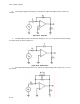
(1) Figure Q-35 shows an inverting amplifier. This can be ascertained by the fact that the input is
applied to the minus terminal of the op amp, indicating that this is the inverting input. Feedback is applied
from the output across R
f
back to the input. Since the output is 180 degrees out of phase with the input,
there will be negative feedback.
Figure Q-35. Inverting Amplifier
(2) Figure Q-36 shows a noninverting amp with feedback going to the inverting input and the same
results will be obtained as with the inverting type amp.