
Service manual


STP 11-25R13-SM-TG
Q - 35
g. J-K Flip-Flop
. The J-K FF is the universal FF. It comes as a synchronous (non-clocked) and
synchronous (clocked). The characteristics of the R-S and T FFs are combined in the J-K FF.
(1) The new designations for the inputs were chosen so that the J-K function can be differentiated
from the R-S functions. The J input can be likened to the S input and the K to the R input.
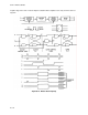
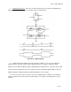
(2) Activation of the J and K inputs simultaneously will cause the output to change state when the FF
is clocked, just like the T FF. The indeterminate state of the R-S FF is not present in the J-K FF because
of feedback. Table Q-19 shows the truth table for the J-K FF and Figure Q-32 shows the gating circuitry.
Table Q-19. Truth Table for the J-K FF
Q-9. Operational Amplifiers (Op Amps).
a. Introduction.
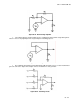
(1) Along with the gating circuits of modem equipment, there is a special IC that can perform several
different functions. Basically, the op amp is just an amplifier. By connecting the external components in
different combinations, this device can take the place of several different circuits.
(2) Most of us are used to transistor circuitry and can recognize the basic circuits. With op amps, the
circuits do the same thing but may not appear the same way. This lesson will assist in identifying these
basic op amp circuits.
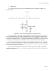
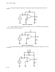
b. An op amp consists basically of three amplifiers.
(1) The main section is a differential amplifier.
(2) Of course, the differential amplifier can not function without a current source control.
(3) The last section is the output amplifier.
NOTE: Normally you will not be dealing with the actual insides of the op
amp. Mostly we will discuss the overall operation and externally
connected components.
J K Qn + 1
0 0 Qn
0 1 0
1 0 1
__
1 1 Qn