
Service manual


STP 11-25R13-SM-TG
Q - 31
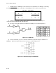
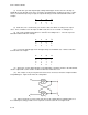
Figure Q-28. Clocked R-S Flip-Flop
Table Q-18. Truth Table for Clocked R-S FF
(3) The clocked R-S FF is the basic circuit from which the remaining FFs will be derived.
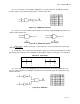
d. Master-Slave Principle
. This far in our discussion, the only use for R-S FFs is as a simple
storage device. As is, if they were used in applications such as counters or shift registers where outputs
from one FF are used as the inputs to the next ones, the data would be almost instantaneously
transferred to the output whenever the input changed. In many cases, this is undesirable.
(1) This problem can be solved by use of external gating circuits but it is more convenient to use a
master-slave principle that will cause the data to be stepped through the logic circuit.
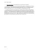
(2) Figure Q-29 shows the basic idea of master-slave. Information at the R and S inputs is stored
in the master flip-flop on the positive edge of the clock and then transferred to the slave FF on the
R S CP Qn + 1 R S Qn + 1
0 0 0 Qn 0 0 Qn
0 0 1 Qn 0 1 1
0 1 0 Qn equals 1 0 0
0 1 1 1 1 1 *
1 0 0 Qn If CP is assumed to be present
1 0 1 0
1 1 0 Qn
1 1 1 * (Indeterminate)