
Service manual


STP 11-25R13-SM-TG
Q - 28
(7) If at this time you made input R high, nothing would happen because the FF is already set.
(NOTE: Most of the time this state can be assumed as the initial inactive condition of most FFs.) Now it
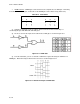
can be seen that when input S goes high, the outputs will change and the truth table will look like this
example.
_
R S Q Q
0 0 0 1
0 1 1 0
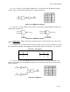
(8) At this time, if S is returned low, you should see that there will be no change in the output
states. This is evident because the inputs to NOR
2
at this time are S = 0 and Q = 1 making Q = 0.
_
(9) This results in NOR
1
having inputs R = 0 and Q = 0 resulting in Q = 1. The next step in the
truth table would look like this example.
_
R S Q Q
0 0 0 1
0 1 1 0
0 0 1 0
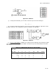
(10) If you make input R high, the FF will again change to the RESET state. Now the truth table
looks like this next example.
_
R S Q Q
0 0 0 1
0 1 1 0
0 0 1 0
1 0 0 1
(11) At this time, assume that both inputs are brought high. Logically it cannot be determined what
state the outputs will assume and this condition should not be allowed to occur.
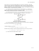
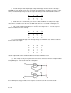
(12) This example is only one way that an R-S FF can be constructed. Another example would be
using NAND gates. Figure Q-25 shows this configuration.
Figure Q-25. R-S Flip-Flop with NAND Gates
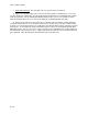
(13) Where the inputs are active in their low state, the FF symbol will have STATE indicators at
the S and R inputs, telling you that a low is required to set and reset the FF as in Figure Q-26.