
Service manual


STP 11-25R13-SM-TG
Q - 27
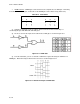
may be new to you. The first is Qn, which indicates the state of Q at a certain time n. Qn usually
represents the state of Q prior to the changing of inputs. All this statement is saying is that when both
inputs are changed to a low state, the Q will not change states. The second new statement is Qn + 1,
which is used to indicate the state of Q after the inputs were changed. As an example, look at the line in
which R = 0 and S = 1. The FF now becomes set and Q = l.
(3) The third statement is the indeterminate state. Meaning that there is no reliable way to
determine how the output states will change if certain inputs are applied. Usually a logic circuit will
employ safeguards against inputs that will cause indeterminate outputs.
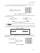
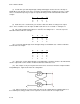
(4) Now that you know how an R-S FF is supposed to function, take a look at how one can be
constructed using basic gates. Figure Q-24 shows using two NOR gates to form an R-S FF.
Figure Q-24. R-S Flip-Flop Construction
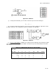
(5) In order to follow this FF through its logical sequence you must first assume a starting point.
The most universal point would be in the reset position with−
_
Q = low and Q = high.
Using this information, you can say if−
_
R = low then Q will equal low because Q = high.
Remember that for a NOR gate’s output to go high, both inputs must be low. Now you can look at
_
S = low and say Q = high because Q = low.
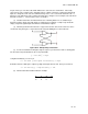
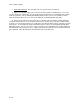
(6) Now the truth table would look like this example.
_
R S Q Q
0 0 0 1