
Service manual


STP 11-25R13-SM-TG
Q - 26
i. Inhibited Gates
. An inhibited gate is a type of gate that has logic level inputs that are different
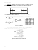
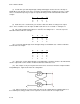
from each other. Figure Q-22 is an example of an inhibited AND gate.
Figure Q-22. Inhibited Gate
(1) Input A must be low and input B must be high to make output C high.
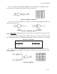
(2) Any type of gate could be arranged to act as an inhibited gate by inverting one or more of the
inputs before the gate itself.
Q-8. Flip-Flops (FF).
Sometimes information must be stored for use later in time than when the information was generated.
A FF can be used to accomplish this storage of data. At other times, there might be a requirement to
count different data. FFs can be used to accomplish this also.
a. A FF is not like the basic gates previously covered in the sense that the basic gate outputs
depend upon the inputs at the time the outputs are observed.
(1) This is not true with FFs. You must not only know what the inputs are but what they were
before. Only then can you predict what the output should be. FFs fall into a class called sequential logic.
(2) In order to troubleshoot circuits containing FFs, you must have a good understanding of what
happens to these units when they go through their sequence of events.
b. R-S Flip-Flops
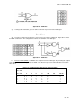
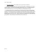
. Figure Q-23 shows the R-S FF consisting of two inputs and two outputs. One
of the inputs is labeled R (Reset) and, when activated, causes the R-S FF to assume the RESET
(CLEAR) condition. When the S (SET) input is activated, the FF assumes the SET condition. The
outputs are
_ _
labeled Q and Q. These outputs are compliments of each other. Therefore when Q = Hi, then Q = Low.
Figure Q-23. R-S Flip-Flop
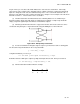
(1) Table Q-16 shows the truth table for the R-S FF.
Table Q-16. Truth Table for R-S Flip-Flop
(2) Notice in the truth table three statements that
R S Qn + 1
0 0 Qn
0 1 1
1 0 0
1 1 * (Indeterminate state)