
Service manual


STP 11-25R13-SM-TG
Q - 24
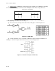
(3) From the truth table in Figure Q-15, you can see that this configuration satisfies the definition of
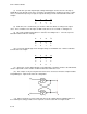
a NOR gate. The second way to perform the NOR function is to feed the inputs into an OR gate and then
invert the output. Figure Q-16 shows this operation.
Figure Q-16. NOR Gate (alternate)
__ _ _
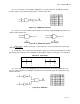
(4) This arrangement also satisfies the definition of a NOR gate and tells us that AB = A + B.
The common symbol is shown in Figure Q-17.
Figure Q-17. NOR Gate Symbol
(5) In our previous discussion of NAND and NOR gates, it was brought out that there are two
symbols for each gate but only one is common to each gate. This is true as long as the IC diagram is
concerned. But on a schematic diagram, they will be found whichever way indicates the active input level
or output level.
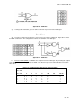
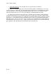
(a) As an example, Figure Q-18 indicates that the active output is low and requires that 1 or more of
the inputs are high.
Figure Q-18. NOR Gate Symbol (common)
(b) In Figure Q-19, the inputs are active when they are low and the output will be high only when all
inputs are low.
Figure Q-19. NOR Gate Symbol (uncommon)
(6) The NOT indicator (-O-) is usually referred to as a state indicator. It indicates what state the
inputs and outputs are in when they are active. So remember that these two gates may appear on a
schematic depending on the desired inputs or outputs from them.
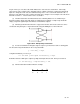
g. Exclusive-OR (XOR) Function
. An XOR gate is an OR gate which gives an output only when
the two inputs are different. Figure Q-20 shows the symbol and truth table for an XOR gate.