
Service manual


STP 11-25R13-SM-TG
Q - 23
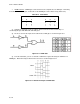
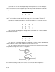
(4) The second way of constructing a NAND gate is to feed the inputs into an AND gate and then
invert the output. This method and truth table are shown in Figure Q-13.
Figure Q-13. NAND Gate (alternate)
_ _ __
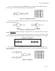
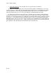
(5) Therefore, as shown in Figures Q-12 and Q-13, A + B = AA. A typical NAND IC would have the
symbol shown in Figure Q-14.
Figure Q-14. NAND Gate Symbol
f. NOR Function
. NOR is another type of gate that can be constructed from the three basic gates
(AND, OR, and NOT).
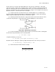
(1) A NOR gate is the complement of the OR gate. Again, you can look at the truth table for an OR
gate and develop a truth table for the NOR gate by inverting the outputs of the OR gate. See Table Q-14.
Table Q-14. Truth Tables
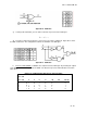
(2) Just as in the case of the NAND gate, there are also two ways to construct a NOR gate. The
first is to feed the inputs into an AND gate after they have been inverted. Figure Q-15 shows this along
with the truth table.
Figure Q-15. NOR Gate
OR Table NOR Table
A B C
A B C
0 0 0 0 0 1
0 1 1 0 1 0
1 0 1 1 0 0
1 1 1 1 1 0