
Service manual


STP 11-25R13-SM-TG
Q - 5
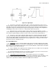
(1) The symbol for disjunction is (+), so the logic function can be written as "A + B = C" and is read
as "A OR B = C".
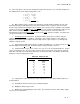
(2) An OR gate is the logic circuit that performs the mathematical operation of disjunction. Table
Q-3 lists all the possibilities for this operation.
Table Q-3. Possibilities for Disjunction
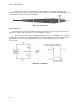
f. Negation
. The last operation is called negation and is defined as follows: if B is the negation of
A, then A is true if B is false and a is false if B is true.
_
(1) The symbol of negation is an overbar placed above a variable, (i.e., B); so the above operation
_ _
is written as "A = B, A = B" and is read as "A is equal to Not B" and as "Not A is equal to B".
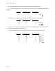
(2) An inverting amp performs the operation of negation. Table Q-4 lists the possibilities for these
statements.
Table Q-4. Possibilities for Negation
g. Truth Tables. The tables that were used in the previous discussion are called truth tables. A
truth table is a listing of all possible input combinations and the outputs that result for the different logic
operations.
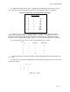
(1) From the previous discussion, you can see that there are 10 postulates (assumed truths) which
can be derived. These are listed in Table Q-5.
Table Q-5. Inputs and Output Results.
(2) Thirteen
theorems can be developed from the above postulates. Since a variable can assume any one of the
A + B = C
A B C
0 0 0
0 1 1
1 0 1
1 1 1
A B
0 1
1 0
P-1 0 AND 0 = 0
P-2 0 AND 1 = 0
P-3 1 AND 0 = 0
P-4 1 AND 1 = 1
P-5 0 OR 0 = 0
P-6 0 OR 1 = 1
P-7 1 OR 0 = 1
P-8 1 OR 1 = 1 _
P-9 0 = NOT 1 (0 = 1
)
P-10 1 = NOT 0 (1 = 0)