
Service manual


STP 11-25R13-SM-TG
Q - 3
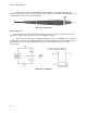
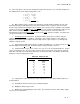
Figure Q-3. High Output
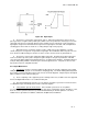
b. The pulser is connected to a typical logic low, 1V. When the push-button is depressed, the
pulser generates a negative and a positive pulse, which causes the point in the circuit to go to zero volts
(still a logic low), then to a logic high, then back to its original 1V level. Effectively, a pulser changes a
logic high to a logic low for an instant and a logic low to a logic high for an instant. This is helpful when
checking gates and sections of circuits to see if they will pass logic levels properly.
c. Although a pulser can change a high to a low to a high, it does have limitations. A pulser
cannot change V
CC
to a logic low or a ground to a logic high. These limitations make the pulser an even
more effective troubleshooting tool, because it can be used to check for shorts to ground and V
CC
.
d. The pulser is often used in conjunction with a logic probe. The initial check when using these
tools is to short the tips of the probe and pulser together and press the pulser push-button. This will
cause the probe light to blink and show that both pieces of equipment are working. Touching both tips to
an IC pin and pulsing it will also show if the pin is shorted to ground at V
CC
. The pulser is also used to
inject pulses into more complicated circuits.
Q-5. Digital Mathematics.
a. Introduction
. Because television equipment, like almost all electronic equipment, is becoming
totally IC-type circuitry, your job as a technician is changing greatly. You will be working with many black
boxes whose actual circuits will not be present on most schematic diagrams. Only the inputs and outputs
will be available for your troubleshooting use.
(1) As the complexity of the equipment you are working on increases, it will become more apparent
how useful digital mathematics is as a troubleshooting tool.
(2) This material will show you how to use the 10 basic postulates to prove the 13 basic theorems
of combination logic, and identify the basic laws of Boolean algebra.
b. Using Number Systems in Electronics
. In the decimal system, there are 10 symbols
(0,1,2,3,4,5,6,7,8, and 9). Placing those 10 symbols into various combinations derives all numbers. Also,
there are certain operations that can be performed mathematically to calculate problems. The most
familiar of these operations are addition, subtraction, multiplication, and division.