
Service manual


STP 11-25R13-SM-TG
Q - 2
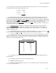
b. When the tip is touched to a pin with logic high, the light becomes bright. When the tip is
touched to ground or a logic low, the light goes out. As you can see, this method of checking logic levels
is much quicker and easier than using a voltmeter.
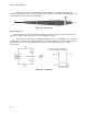
Figure Q-1. Logic Probe
Q-4. Logic Pulser.
The logic probe is not the only troubleshooting tool used in logic circuits. Another useful tool is the
logic pulser. Like the probe, the pulser uses a +5V supply for its power.
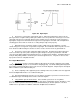
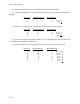
a. The main use for the pulser is changing existing logic levels in a circuit (Figure Q-2). In Figure
Q-3, the pulser is connected to approximately 4V. This is a typical voltage for a logic 1. When the pulser
push-button is pressed, it causes that point in the circuit to go to a logic 0, or low, for about 0.3
microseconds.
Figure Q-2. Low Output