
Service manual


STP 11-25R13-SM-TG
Q - 1
APPENDIX Q – LOGIC CIRCUITS GUIDELINES
(INCLUDING DIGITAL MATHEMATICS)
Q-1. Introduction.
Troubleshooting digital circuits is not much different from troubleshooting circuits with discrete
components. Either the circuit performs correctly or it does not. One advantage of digital circuits is that
there are only two voltage levels to check, high and low. If both of these voltages are correct, the
problem is normally in an integrated circuit (IC) or a run.
a. The first step in troubleshooting is verifying that the circuit is not operating correctly. With some
logic circuits, this may simply be checking a truth table. In large, complicated circuits, the malfunction
must be isolated to one stage; then that stage must be checked.
b. All ICs, except for special function chips, must have ground and V
CC
for current to flow to the
internal circuitry. If either of these is not present, the IC cannot function. When one chip has an incorrect
output, all the ICs after the malfunctioning chip will have improper inputs, and therefore, improper outputs.
It is usually best to start at the output of a circuit and work the half-split method as much as possible.
c. When you do not know where the malfunction is located, the pulser can be used to inject
signals into the circuit at any given point. This will verify if the gates after the injection point are good or
not. If these gates prove to be good, go back farther in the circuit and try again.
Q-2. Checking Truth Tables.
NOTE: Refer to the circuit in Table Q-1 (A and B).
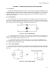
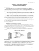
a. Table Q-lA is the correct truth table; Table Q-lB is the malfunctioning truth table. Since the
output goes high and low, the output from the OR gate is okay. The logical place to check is the inputs to
the AND gates. The malfunction in this circuit is A input to IC1 is open. Troubleshooting is mostly done
in your head, with only enough measurements taken to prove your theories.
b. In many cases, the malfunction can be found from an examination of the truth table, as in
Table Q-1.
Table Q-1 (A and B). XOR Circuit
Q-3. Logic Probe.
When troubleshooting circuits built with discrete components, you used a voltmeter to measure
voltages. In logic circuits there are only two voltage levels, high and low. A logic probe is used to monitor
highs, lows, and opens. The ICs used in this section use +5 (HIGH) and zero (LOW) volt levels.
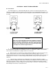
a. The logic probe (Figure Q-1) has a small light located near its tip. This is the indicating device.
When the light is dim, as it will be when you apply power to the probe, there is an open circuit, or no
current flow. In ICs an open is seen as a logic high to the components.