
Service manual


STP 11-25R13-SM-TG
P - 1
APPENDIX P – ZENER DIODE AND REGULATOR GUIDELINES
P-1. Zener Diode.
A solid-state diode may develop either an open or a short; that is, its resistance may approach zero
or infinity in both the forward and reverse directions. Normally, the forward resistance of a diode should
be much lower than its reverse resistance. In the Zener, due to its heavy doping, its reverse resistance
can be broken down much more easily than a regular diode. Excessive current is often the cause of
trouble in the Zener diode.
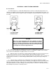
P-2. Zener Regulator.
In the circuit in Figure P-1, if the Zener diode opens, it no longer has any effect on the circuit. The
circuit is no longer able to regulate the output voltage, so any increase or decrease in the input voltage
will result in a corresponding change in the output voltage. If the Zener diode were too short, this would
place a direct short across the load and the output voltage would fall to zero.
Figure P-1. Zener Voltage Regulator
a. If the internal resistance of the Zener diode decreases to a value that is too low, it will pass too
much current through the series resistor (R). As a result, R will drop too much of the input voltage and
this will cause the regulated output voltage to be too low.
b. If the internal resistance of the Zener diode increases to a value that is too high, the series
resistor will not receive enough current. As a result, R will not drop enough of the input voltage and so
the regulated output voltage will be too high.
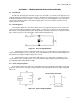
P-3. Series Voltage Regulator.
In the circuit in Figure P-2, if Ql opens, continuity between the load and the input power source will
be broken. Since there is no longer a complete path for current through the load, the output voltage will
fall to zero.
Figure P-2. Series Voltage Regulator