
Service manual


STP 11-25R13-SM-TG
O - 3
Some circuit applications require an input waveform that is clamped to some DC level other than
zero volts or ground. To obtain this type of clamping, a biased clamper is used.
a. Clamping may be to a positive or negative level. Except for the addition of a fixed voltage in
series with the diode, these circuits operate exactly the same as unbiased clampers. The bias voltage
determines the level to which the waveform will be clamped.
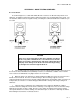
b. Figure O-2 shows the positive diode clamper with a positive bias connected. Note that the
diode is forward-biased by the battery. Therefore, without a signal applied, the output terminal is at the
battery voltage due to diode conduction.
Figure O-2. Positive Diode Clamper with Positive Reference Level
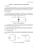
c. Figure O-3 shows positive diode clamping to a negative bias level.
Figure O-3. Positive Diode Clamping to a Negative Bias Level
(1) The top place of C is also at the same voltage. The negative half cycle of the input waveform
forward-biases the diode. The diode conducts and charges C to the additional peak voltage.
(2) On the positive half-cycle C tries to discharge, but the long time constant maintains its charge
nearly constant as described before. The diode conducts only enough to replace any charge lost by the
capacitor.
(3) Note that the bias voltage level is the voltage level to which the output waveform is clamped.