
Service manual


STP 11-25R13-SM-TG
O - 1
APPENDIX O – CLIPPER AND CLAMPER CIRCUITS GUIDELINES
O-1. Introduction.
Diode clipper circuits consist primarily of a diode and a resistor, where the diode is in series or
parallel with the output signal. The clamper adds a capacitor to the circuit and there are various
arrangements for this circuit. These circuits can have either positive, negative, or zero bias applied. The
most probable cause of a problem in such circuits is a change in the resistance value of the diode or
resistor due to an open or a short. Occasionally the resistance value will change due to a partial short but
this is more unlikely than the complete short.
O-2. Clipper Circuits.
The basic test equipment essential to troubleshooting the diode clipper circuit is a multifunction
meter and an oscilloscope.
a. The oscilloscope is used to check input and output wave shapes.
(1) If a check of the output of a diode clipper or clamper circuit with zero bias gives no indication of
an output, the first step is to check the input to the circuit. When there is no input signal, it can be
assumed that the circuit is operating normally.
(2) If the input signal is present, the individual component voltage and resistance should be
checked to determine if each component is functioning properly.
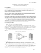
b. The multifunction meter is used to check DC voltages and resistance values. In addition to
checking the resistance of the resistors, the meter can be used to check the front-to-back resistance ratio
of the diode.
(1) In-circuit measurements of voltage and resistance can be made without completely isolating the
circuit and these readings can be compared with readings from an operational circuit. This should be
helpful in isolating the malfunction to a particular circuit.
(2) When the above action is completed, the circuit should be isolated before making final
resistance measurements. If the clipper circuit is mounted on a printed circuit board, the board should be
removed from the operational unit before final resistance measurements are made.
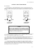
O-3. Diode Clipper.
a. In a circuit where the output is taken across the resistor and no clipping action is present, a
quick check of the diode should reveal the problem. An open in any part of the circuit prior to the output
jack will result in no output.
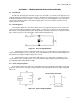
b. Series and parallel diode clipper circuits with either positive or negative bias will have only a DC
level at the output if an open occurs in the circuit prior to the point where the output is taken.
(1) If the open occurs between the output jack and bias voltage, the reference voltage and output
signal will not be present in the output; but this may be difficult to verify. Isolation of the circuit and a
continuity check of the circuit should reveal the problem.
(2) An open in either diode of a double-diode clipper would cause the circuit to act as a parallel
clipper.
O-4. Clamper Circuits.