
Service manual


STP 11-25R13-SM-TG
N - 1
APPENDIX N – DIODE TESTING GUIDELINES
N-1. Introduction.
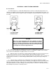
As shown in Figure N-1, a diode will exhibit different resistances for different lead positions of an
ohmmeter. A multimeter, when placed in the ohmmeter function, has a polarity applied to its leads. You
can determine which lead is the negative lead by consulting the technical manual for the multimeter you
are using.
Figure N-1. Ohmmeter Checks
CAUTION
Never use a range setting below ohms times 100 when checking a
diode or any other solid-state device. An ohmmeter uses internal
power for resistance measurements; low range settings (below R x
100) may cause damage to the diode. The lower the range setting
is, the higher the current through the diode is.
a. If the negative lead of the ohmmeter is placed on the cathode and the positive lead is placed on
the anode, the meter will indicate low (minimum) resistance, a forward-bias condition. If the leads are
reversed, the meter will indicate very high resistance or reverse bias.
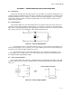
b. When the range of an ohmmeter is changed, different multimeter resistors are placed in series
with the meter movement. Therefore for different ranges, different voltages appear across the
component being measured. Because the bias voltage applied varies the depletion region (resistance) of
a PN junction, the resistance of a diode will appear different with a change in the range setting of an
ohmmeter.
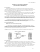
c. Using the ohms x 1,000 range, the reading taken on the ohmmeter will indicate a higher
resistance than the reading taken on the ohms x 100 range. This happens because of the lower voltage
applied to the junction on ohms x 1,000. Because of the change in voltage between ranges and the
consequent variation in resistance readings, it is advised that you use the ohms x 100 range at all times
when making measurements of solid-state devices.