
Service manual


STP 11-25R13-SM-TG
M - 1
APPENDIX M – TRANSFORMER GUIDELINES
M-1. Introduction.
Transformers (XFMRs) are extremely reliable devices because they have no moving parts to wear
out. Most XFMRs fail due to current overload. The maximum current that can be drawn from the
secondary normally rates XFMRs. As long as these currents are not exceeded, XFMRs normally have a
long operational life. However, other circuit component failures can cause excessive current and XFMR
damage.
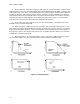
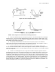
M-2. Open Windings.
Excessive current in either the secondary or primary can cause excessive heat. If the duration of the
overload is long enough, then the conductors may become hot enough to burn open. An open winding
stops current flow and XFMR operation. Opens in the secondary can be located because of an absence
of voltage. An open in the primary cannot be detected by voltage tests because the source voltage is still
present. When open windings are suspected, the power should be removed and the windings should be
tested for continuity. The normal winding resistance is generally quite small (a few hundred ohms) and
the ohmmeter provides valid tests for continuity.
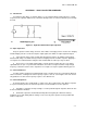
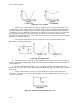
M-3. Shorted Windings.
Excessive current can also melt the insulation between the windings, permitting them to short
together. When the complete winding shorts, current will be excessive, no voltage will be developed, and
the protective fuse or circuit breaker will open. Under these conditions, testing must be done without
applied power. Continuity testing on a low resistance range may indicate reduced or no resistance in the
shorted winding. The resistance of the primary winding is often only a few ohms, so testing and analysis
must be performed carefully, as in a power XFMR, where the windings are often less than one ohm
because of the large wires that are used.
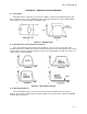
a. Partial Shorts. A partially shorted winding will develop below normal voltages. Current will
increase and cause excessive XFMR heating. If the XFMR is operating hotter than normal, then all
voltages should be tested to see if one is low (indicating a partial short) or if excessive current is being
drawn by the connected load. Final testing may require testing the load current connected to each
winding.
b. Other Shorts. Sometimes when the secondary is wound over the primary, overheating can
cause a short between the primary and the secondary. Such a short will normally cause excessive
current and activate the safety device. Continuity testing of a XFMR should always include a test from
the primary to the secondary to ensure that no short or leakage path exists. XFMR testing should also
include a continuity test from the primary to the frame and from the secondary to the frame (XFMR case).
Only an indication of infinity is acceptable. Leakage or shorts to the case can cause overheating as well
as a shock (safety) hazard.
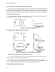
M-4. Alternate Method of Troubleshooting.
Another method of troubleshooting XFMRs, especially partially shorted windings, is by comparison.
If you have a good spare replacement XFMR, you can measure the windings on the spare and compare
those readings to the suspected bad XFMR. Sometimes the schematic diagram will indicate the
approximate resistances of the windings.