
Service manual


STP 11-25R13-SM-TG
K - 4
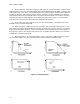
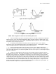
Figure K-7. L2 or C2 Open
e. If either series component (Ll or Cl) were to completely short, the entire series portion of the
circuit would be shorted. Without any series impedance in the circuit, the voltage normally dropped by
the tank would have to be dropped by the load. Once again, the whole circuit would be less efficient at
rejecting the frequencies within the rejection band. As with any short, burnout could occur. This would
be very likely at or near the resonant frequency of L2 and C2 because their net reactance would
approach zero, thus shorting out the entire circuit. So a shorted series component in the circuit of Figure
K-6 could cause multiple problems.
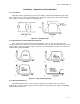
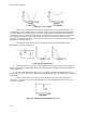
f. If the band reject filter was like the one on Figure K-8A, the circuit would behave a little
differently if a malfunction developed.
Figure K-8. Band Reject Filter
g. If the inductor were to open, the circuit would behave like a high pass filter, and the frequency
response curve would resemble Figure K-8B. The lower frequencies would be attenuated much like the
curve in Figure K-6.
h. An open capacitor would result in a curve as in Figure K-8C; this curve indicates the circuit
would act like a low pass filter. This is similar to the attenuation of the higher frequencies that occurred in
Figure K-5B.
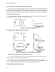
i. If either component were to short, the resistor would have to drop all of the voltage at all
frequencies. The response curve would look like Figure K-9. Once again, burnout could occur due to
excessive current flow.
Figure K-9. Shorted Component Response Curve