
Service manual


STP 11-25R13-SM-TG
K - 3
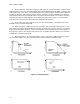
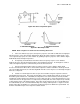
Figure K-5. Series Component Opens
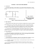
Figure K-6. Band Reject Filter
NOTE: Refer to Figures K-5 and K-6 for the following discussion.
a. If the series inductor (Ll) opens, the frequency response curve will resemble that of a high pass
filter because the series capacitor (Cl) will attenuate (block) the lower frequencies (Figure K-5A). If the
series capacitor (Cl) opens, the series inductor (Ll) yielding a frequency response curve similar to Figure
K-5B will attenuate the higher frequencies.
b. A completely shorted inductor L2 would result in a frequency response curve similar to
Figure K-5B, since capacitor C2 would act like a short at higher frequencies. As C2 begins to act like a
short at the higher frequencies, it will effectively short out the load as well.
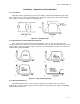
c. A shorted capacitor C2 will result in a frequency response curve similar to Figure K-5A,
because the inductor L2 will act like a short at lower frequencies and the load will be effectively shorted
out as well. With either short, the current being drawn from the source may rise to a value high enough to
burn out a component.
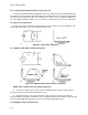
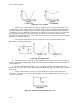
d. If either L2 or C2 in Figure K-6 were to open, there would no longer be a path for current in
parallel with the load resistor. This means the impedance of the network that is made up of L2, C2, and
R would be greater than before. Meanwhile, the impedance of the other network (Ll and Cl) would be
unchanged. Realize that the two networks are in series with each other. Next remember that in a series
circuit, an increase in the opposition of a component (or network) will cause that component (or network)
to drop a bigger share of the applied voltage. In the filter circuit of Figure K-6, the net result will be that
the network made up of R, L2, and C2 will now drop more voltage at all frequencies. Figure K-7 shows
that the entire filter circuit will be less efficient at rejecting the frequencies within the rejection band. Or,
the filter circuit will now pass more frequencies than it should.