
Service manual


STP 11-25R13-SM-TG
K - 1
APPENDIX K – BANDPASS FILTER GUIDELINES
K-1. Introduction.
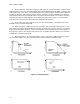
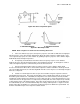
A bandpass filter is designed to pass frequencies within a continuous band, limited by upper and
lower cutoff frequencies, and to substantially reduce or attenuate all frequencies above and below that
band. Figure K-1 shows an example of a bandpass filter.
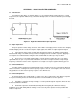
Figure K-1. Bandpass Filter
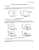
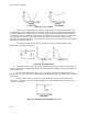
K-2. Open Capacitor in the Parallel LC Tank Circuit.
If the capacitor in the parallel LC tank circuit in Figure K-1 were to open, the upper end of the
bandpass frequencies would be increased to a higher frequency before the cutoff frequency was reached
(Figure K-2B). The lower end of the frequency response curve would change very little or not at all. The
result would be a wider bandwidth.
Figure K-2. Open Parallel Capacitor
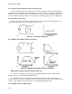
K-3. Open Parallel Inductor.
If the parallel inductor were to open, the lower cutoff frequency would be lower as shown in
Figure K-2C. The upper cutoff frequency would be normal or very nearly normal. Again, the bandwidth
would be wider than normal.