
Service manual


STP 11-25R13-SM-TG
G - 1
APPENDIX G – DIFFERENTIAL AMPLIFIER GUIDELINES
G-1. Modes of Operation.
The differential amplifier has different modes of operation and so the symptoms caused by
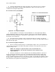
malfunctions may not always be the same. Study the schematic diagram (Figure G-1) to determine which
mode of operation is being used and then consider the trouble symptoms with respect to that mode of
operation.
Figure G-1. Differential Amplifier
G-2. Signal Tracing.
Signal tracing is effective to determine the presence or absence of the input signal(s), and it may
indicate that it is not operating or is operating incorrectly. When the oscilloscope has revealed the
defective stage, voltage tests followed by resistance and continuity tests will usually locate the trouble
quickly. Standard troubleshooting procedures apply but knowledge of circuit operation and an ability to
read and analyze schematic diagrams is necessary.
a. In Figure G-1, Tl with its associated circuitry supplies signals to the bases of Ql and Q2. These
two signals are 180 degrees out of phase. If a signal does not appear at the base of Ql or Q2, check Tl
and its associated circuitry.
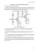
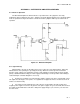
b. If no signal or a low signal appears at the collectors or Ql and Q2, check the positive and
negative power supplies in reference to ground. If the power supplies are good, check R4; R4 can affect
the outputs of Ql and Q2 at the same time. Bad power supply voltages (+V
CC
and -V
CC
) can also have
the same effect.