
Service manual


STP 11-25R13-SM-TG
F - 2
j. If the transistor in the circuit is suspected of being at fault, isolate the leads and check the front-
to-back resistance ratios of the emitter-base junction and the collector-base junction. A high-resistance
reading in both directions is an indication of a probable malfunction. An in-circuit check of the transistor
can be made and the readings compared with an operational circuit. This process is helpful when the
leads of the transistor cannot be isolated.
k. A summary of the basic steps in troubleshooting is as follows:
(1) Determine the malfunction.
(2) Make initial checks.
(3) Locate the faulty stage of the circuit.
F-2. Theoretical Troubleshooting of MVs.
In this discussion you will analyze malfunctions of the astable, bistable, and monostable MVs.
a. Astable MV.
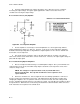
(1) Using the circuit in Figure F-1, assume that the collector of Ql opens. The first step, as with all
troubleshooting, is to check the output. If there is an output, the circuit is oscillating. If not, then the
circuit is obviously not oscillating. At this point the oscilloscope will no longer be useful except to check
DC potentials.
Figure F-1. Astable Multivibrator
(2) The next step is to check these DC potentials. With the collector of Ql open, it obviously cannot
conduct. Therefore, the other transistor (Q2) must be conducting. This can be verified by the DC
potentials at the collector, base, and emitter of each transmitter.
(3) If any one of the PN junctions of the two transistors were to open or short, there would be no
output pulses. An in-circuit resistance check of these junctions compared with known good readings
could determine the condition of the transistor.
(4) A change in the resistance of either collector load resistor would affect the gain of the stage and
would therefore affect the amplitude of the output pulses. An open in either collector resistor would
eliminate the output pulses.