
Service manual


STP 11-25R13-SM-TG
E - 1
APPENDIX E – RC COUPLED AMPLIFIER GUIDELINES
E-1. Troubleshooting RC-Coupled Amplifiers.
When there is no AC signal output, or if the output is weak or distorted, it is assumed that the trouble
has been localized to the amplifier circuit by noticing the input signal is normal but the output is abnormal.
General practice is to check the transistor first, since the transistor is the most likely cause of the trouble.
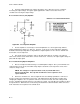
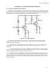
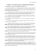
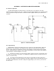
If the transistor is good, follow the following steps to find the trouble (Figure E-1).
Figure E-1. RC-Coupled Amplifier
a. Measure the DC voltages at the collector, base, and emitter of the transistor, looking for
readings that are too high or too low. Measure the V
CC
voltage as well, since all other DC voltages
depend on the DC supply voltage.
b. When one of the element voltages measures too high or too low, check its associated circuit.
After turning off the power and isolating, measure with an ohmmeter to find an open or shorted
component.
c. Even if all the DC voltages are normal, the amplifier can still have an open coupling or bypass
capacitor. A shorted capacitor affects DC voltage readings, but an open capacitor is best found by being
temporarily bridged with another capacitor of about the same size.
d. When the defective component has been found, a new component of the same value or close
to it is soldered in its place. If a burned-out resistor is replaced, look for a bypass capacitor in the same
circuit and check it too, since a leaky or shorted capacitor can be the cause of the open resistor. In high-
frequency circuits, do not replace mica or ceramic capacitors with the rolled-foil type because of their
different inductances.