
Service manual


STP 11-25R13-SM-TG
D - 4
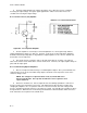
b. A positive signal applied to the emitter, through Cl, causes Ql to decrease its conduction,
increasing the output voltage. A negative signal applied to the emitter causes Ql to increase its
conduction, decreasing the output voltage.
D-7. Common Collector (CC) Amplifier.
Table D-3. CC Component Functions
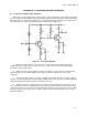
Figure D-4. CC Component Amplifier
a. The CC amplifier is used mostly for current amplification. Its current gain is high, while its
voltage amplification is always less than one. However, it can also be used for impedance matching.
Remember that the input impedance is high while the output impedance is low. Refer to Table D-3 for
the function of each component.
b. This circuit operates exactly the same as the CE circuit, with one exception. The output is
taken off the emitter resistor rather than a collector load resistor. Therefore, the output signal is always in
phase with the input signal.
D-8. Troubleshooting Bipolar Amplifiers.
a. Effects of Component Value Changes on a CE Amplifier's Output. Since you know what each
component does in the circuit, it should be fairly simple to determine each component's effect on the
circuit, if it changes value.
NOTE: The changes in component values for Cl, C2, and C3 will not be
discussed at this time. The only time we will refer to these capacitors is for
opens and shorts.
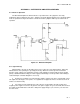
b. Rl Increase and Decrease. Refer to Figure D-2 for the following explanations. If Rl were to
increase in value, there would be less base bias. This will change the Q point on the load line, thus
changing the amplifier's class of operation. If Rl were to decrease in value, base bias voltage would
increase, changing the Q point and class of operation once again. The only difference would be to where
the Q point moves. With a decrease in Rl, the Q point would move toward saturation, while an increase
in R1 would cause the Q point to move toward cutoff.