
Service manual


STP 11-25R13-SM-TG
D - 1
APPENDIX D – COMMON EMITTER, COMMON BASE, AND COMMON
COLLECTOR AMPLIFIERS GUIDELINES
D-1. Introduction.
If there is an input signal to the amplifier but no output signal or a distorted output signal, then the
trouble is localized to the amplifier. It must be determined whether the trouble is caused by the transistor
or by other circuit components.
a. Voltage testing will usually determine if the transistor is or is not conducting. Analysis of the
voltage measurements will probably determine the general area of the trouble. Resistance and continuity
testing in the suspected area will locate the trouble.
b. The schematic diagram must be closely observed to prevent false conclusions. Parallel paths
and conduction through transistor junctions can be misleading without study of the diagram. A logical
testing procedure must be developed and followed to troubleshoot efficiently. A consistent
troubleshooting procedure should always be followed.
D-2. Waveform Troubleshooting.
When looking at the output of an amplifier and you know what kind of output it should have, such as
a class A output, but instead you observe a class B output, you know something is wrong. There are
certain components that can cause this problem and you can easily avoid costly "shotgun" guesses by
knowing the possibilities available to you.
D-3. Common Emitter (CE) Waveforms.
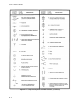
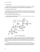
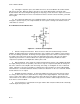
a. Distorted Outputs. Refer to Table D-1 and the explanation of the base bias resistor in Figure
D-1.
(1) Notice that the base bias resistor affects the Q Point on the load line, which in turn will affect the
class of operation of the amplifier.
(2) Another component that can affect the class of operation of the amplifier is the swamping
resistor. When the swamping resistor shorts, the emitter is referenced to ground and the base voltage
will thus change to roughly 0.7V above the ground reference. This means that the Q point will be 0.7V
(C3 can cause the same problem when shorted).
(3) The components that can cause a change in the output as far as class or operation are R1
(base bias resistor), R4 (swamping resistor if shorted), and the transistor itself.
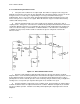
b. Amplitude and Phase Changes. There are other types of waveform changes, such as
amplitude changes: the lower- or higher-than-normal gain of an amplifier, and the in-phase output.
(1) The load resistor and the bypass capacitor are the two biggest culprits when discussing
amplitude or gain changes in waveforms from an amplifier. The load resistor is directly responsible for
the amplitude of the output, and if it shorts then it cannot develop an output. If it opens then there is no
current flow to develop an output. Thus, the only way the because of the load resistor is by changing its
value as discussed before.