
Service manual


STP 11-25R13-SM-TG
C - 4
C-7. Troubleshooting Oscillator Circuits.
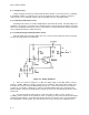
a. If the phase shift oscillator has no output signal, there will be no signal present at any point
within the circuit because it develops its own signal with only a DC voltage applied. However, the circuit
in Figure C-3 has a second stage, so signal tracing is necessary to determine which stage is
malfunctioning. There is no need for using external triggering when troubleshooting because the only
interest is the presence or absence of a signal. When the defective stage is located, troubleshooting
continues with voltage testing.
b. It must be determined if the cause of the trouble is in the transistor circuit, phase shift, or
coupling circuits. Voltage tests of the transistor's terminals will generally indicate whether the transistor is
conducting. When the transistor is not conducting, the voltage test will usually indicate the trouble area,
such as no collector voltage, no forward bias, or similar indications. If the transistor is conducting but
oscillations are not present, then the trouble is isolated to the passive component external to the
transistor circuits.
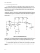
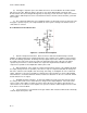
Figure C-3. Phase Shift Oscillator Circuit
c. Resistance and continuity testing will usually isolate the defective part, but the schematic
diagram must be used to determine parallel paths and conduction through the transistor junctions caused
by the ohmmeter battery. Conclusive in-circuit tests of capacitors may be different because of these
parallel paths for current. Shorted capacitors can be located by using an ohmmeter, but you might have
to bridge across a suspected open capacitor with a good one to determine if it is open.
d. Transistor Ql and its components are the oscillator circuit. Transistor Q2 is an emitter follower
isolation circuit that isolates the output terminal from the oscillator. With this arrangement, the load will
not affect oscillator operation. Variable resistor R10 permits adjusting the output signal to the desired
amplitude.