
Service manual


STP 11-25R13-SM-TG
C - 3
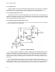
c. Now suppose that when you checked the output of the Hartley oscillator there was no AC
output, but a check of the tank circuit indicated that it was working normally. Then the most likely cause
of the malfunction would be the amplifier. If Ql were to open or short, the voltage readings present on the
elements of the transistor would be quite different from the readings present when the transistor is
operating normally. A comparison between these readings is a good place to start. If Ql were shorted,
current through the transistor would increase and the voltage at the collector would decrease. An open in
Ql would cause all collector current to cease and the voltage would increase. To verify this condition,
isolate Ql from the circuit and take front-to-back resistance readings across the different junctions.
d. Before assuming that the transistor itself is bad, resistance checks need to be made from each
transistor lead to the next component. Remember, for this check to be completely valid you must take
into consideration alternate paths of current in the circuit when the meter is connected. Another method
to ensure validity is to isolate each area that is to be checked.
(1) First, check from the emitter to the junction of Ll and L2. It should show continuity.
(2) Next, check from the base to both C3 and Rl. It should show continuity.
(3) Finally, check from the collector (usually the case of the transistor) to R2. It should show
continuity. If instead you get a very high-resistance reading, the possibility exists that there is an open
between R2 and the collector of Ql.
e. Upon evaluation of the above conditions, it is determined that the connection between R2 and
the collector of Ql is open; before desoldering to isolate, look at the circuit to see if something obvious
has occurred. If nothing is obvious, connect a jumper between the collector and R2. If oscillations start,
repair the broken connection. If oscillations do not start, the problem is most likely internal to the
transistor and the transistor requires replacement.
C-6. Crystal Oscillator Troubleshooting.
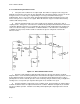
a. If the AC output from the circuit in Figure C-2 ceases, we must troubleshoot the circuit and try to
isolate the stage that has the malfunction. Remember to follow the basic approach to troubleshooting
sinusoidal oscillators as previously discussed in this section.
b. If too much voltage is fed back from the drain to the gate, the crystal will vibrate so violently that
it may crack. Another factor that will affect the crystal is its temperature. When the temperature of a
crystal changes, so does its frequency. In a critical application, the crystal should be kept in
thermostatically controlled ovens where the temperature is carefully controlled. In less critical
applications, the crystal is simply kept in a special holder designed for this purpose without any attempt
being made to maintain a constant temperature. In such cases, changes in the ambient temperature will
have some effect on the output frequency. Regardless of this disadvantage, oscillator stability is still
excellent and superior in respect to conventional oscillators.
c. Besides the crystal in a crystal oscillator, the stage that is most likely to develop a problem is
the amplifier (FET). A change in the biasing network of this circuit will have a definite effect on the
operation of the amplifier. If there is an output from the crystal oscillator but the amplitude or shape of the
output waveform has changed, then a check of the individual voltage drops or resistance values of circuit
components would be in order. At this level of troubleshooting, we will only be dealing with problems that
involve shorted or open components. Remember a change in the voltage reading on the drain or source
leads of the FET may indicate a short or open between the internal elements of the FET.