
Service manual


STP 11-25R13-SM-TG
C - 2
C-3. Voltage Testing.
Voltage testing at the transistor terminals will determine whether or not the transistor is conducting.
If conducting, and there is a problem in the circuit, the trouble must be in the feedback or frequency
control circuits. If not conducting, voltage values may indicate the area of probable trouble.
C-4. Continuity and Resistance Tests.
Continuity and resistance tests will normally indicate and confirm the trouble. Carefully analyze the
schematic to prevent false conclusions due to alternate paths for current when measurements are being
taken before isolating the particular area of the circuit under test. Remember that the transistor junctions
can be forward-biased by the ohmmeter battery.
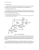
C-5. Troubleshooting the Hartley Oscillator Circuit.
If the AC output from the circuit in Figure C-2 ceases, then we must troubleshoot the circuit and try
to isolate the stage that has the malfunction.
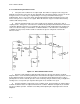
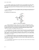
Figure C-2. Hartley Oscillators
a. In this case, the base voltage is +1.1 VDC, the emitter voltage is +0.4 VDC, and the collector
voltage is +6 VDC. With these voltages, the transistor is conducting. This means that the trouble must
be in either the tank circuit or in the DC blocking capacitor C3. If you look at both sides of C3 with an
oscilloscope, you would see that the base side has a potential while the tank side is at ground. This
indicates that the capacitor is probably good (it could be open, but more than likely the problem is in the
tank circuit).
b. In troubleshooting the tank circuit, the oscilloscope will be of little use if the circuit is not
oscillating. Now resistance checks would be in order. To do this you must isolate the tank circuit and the
capacitor from the inductor. The inductor will show a low value of resistance unless it is open and then
the reading will be extremely high. The capacitor will show a very low-resistance reading if shorted.