
Service manual


STP 11-25R13-SM-TG
C - 1
APPENDIX C – OSCILLATOR CIRCUIT GUIDELINES
C-1. Vibrating Frequency.
The natural vibrating frequency of a crystal depends on its size and how it is cut from the basic
crystal (XTAL) material. The thickness of the crystal is the predominate factor in determining the vibrating
frequency. The thinner a crystal is cut, the higher its natural vibrating frequency is. Obviously, when cut
too thin, the crystal will be too fragile for practical use. This places an upper limit on the vibrating
frequency of approximately 50 MHz.
a. In order to connect the crystal into the oscillator circuit, it is placed in a crystal holder. The
holder is made of two metallic plates arranged so that the crystal can vibrate in between them.
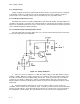
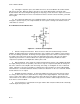
b. Figure C-1 illustrates a crystal equivalent circuit and the schematic symbol. Crystals are only
used in oscillators operating in the radio frequency (RF) ranges.
Figure C-1. Crystal Schematic Symbol and Equivalent Circuit
C-2. Troubleshooting Oscillator Circuits.
As in troubleshooting any other circuit, try to isolate the stages before looking at specific
components. The test equipment and tools used for troubleshooting can vary from common to highly
specialized equipment. The instruments considered essential for sine wave oscillators are a multifunction
meter and an oscilloscope.
a. Voltage measurements are often the fastest way to isolate troubles in any electronic equipment.
Resistance measurements can be used to detect changes in values of resistors and can quickly locate
shorts or opens. DC current measurements can also be helpful in tracking down troubles. In the sine
wave oscillator it is recommended you use a multifunction, high impedance meter to perform these
functions.
b. The oscilloscope is useful to determine whether or not the circuit under test has an output
signal. However, if the oscillator tank circuit has no output signal there would not be any signals in the
circuit, making the oscilloscope useless for isolating the stages. It may be used to measure DC
potentials.
c. If a multifunction meter is used to make voltage measurements, measuring the base voltage will
indicate the presence of oscillations if the circuit is operating class C. Oscillator amplifiers operate class
C of efficiency, but they can be operated in many different classes. If the oscillator is operating class C
and is oscillating, reverse bias can be measured. If the oscillator is not oscillating, forward bias will
usually be present. The DC voltmeter used should have high impedance, so that it will not act as a low-
resistance shunt across the elements of the transistor.