
Service manual


STP 11-25R13-SM-TG
B - 1
APPENDIX B – BASIC CIRCUIT GUIDELINES, TIPS, AND
COMPONENT SYMBOLS
B-1. Introduction.
This appendix covers the basic fundamental troubleshooting procedures that can assist the trainer
and soldier to complete tasks referred to in this appendix. This reference does not cover specific
malfunctions with an individual piece of equipment, but lists tips for basic troubleshooting procedures and
provides some basic guidelines for troubleshooting the most common circuits found in most electronic
equipment
B-2. Basic Troubleshooting Procedures.
These procedures are arranged in a sequence that checks the simple trouble possibilities.
a. Check Control Settings. Incorrect control settings can indicate a trouble that does not exist. If
there is any question about the correct function or operation of any control, refer to the operation and
installation manual.
b. Check Associated Equipment. Before troubleshooting the instrument, check that the applied
signal is correct and properly connected. Check that the probe, if used, is properly compensated and not
defective.
c. Sectionalize Trouble to a Circuit. If the instrument is at fault, isolate the trouble to a circuit by
noting the trouble symptoms. This can be accomplished by using the main panel controls and observing
the signal output or display to identify the nature of the trouble.
d. Visual Check. Visually check the portion of the instrument in which the trouble is suspected.
Some troubles can be located by checking for unsoldered connections, broken wire, loosely seated
transistors, loose fitting connectors, damaged components, or damaged circuit boards.
e. Check Voltage and Waveforms (Localize). Often the defective stage or component can be
located by checking for correct voltages or waveforms in a circuit.
NOTE: Typical waveforms and voltages are given near the diagrams. To obtain
operating conditions similar to those used to take these waveforms and voltages,
refer to the diagrams and instructions of the manufacturer's manual.
f. Check Individual Components. When you have isolated the trouble to one circuit or state, the
next step is to isolate the trouble to one component or part. Disconnecting one end to isolate the
measurement from the effect of the surrounding circuitry best checks components that are soldered in
place. The following methods are provided for checking individual electrical components in the
instrument.
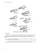
(1) Transistors. The best check for transistor operation is actual performance under operating
conditions. If a transistor is suspected of being defective, substituting a new component or one that has
been checked previously can check it. However, check the circuit conditions carefully so as not to
damage a replacement transistor. If substitute transistors are not available, use a dynamic tester to
check the transistor.
(2) Integrated Circuits (ICs). ICs should not be replaced unless they are actually defective. The
best method for checking these devices is by direct substitution with a new component or one that is
known to be good. Be sure that the circuit conditions are not such that a replacement component might
be damaged.