
Service manual


STP 11-25R13-SM-TG
A - 10
A-11. General Soldering Procedures.
Whenever practical, connections shall be mechanically secure prior to soldering. Soldering of a
connection shall be accomplished in such a manner as to aid the mechanical strength, increase the
electrical conductivity, and provide an airtight covering to prevent corrosion from developing between the
wire and the terminal. Do not use activated flux-cored solders (acid) and activated liquid (paste) fluxes
unless specifically directed.
A-12. Solder Connection Criteria.
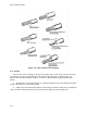
Figure A-15 shows the criteria for a properly completed solder connection.
Figure A-15. Solder Connections
a. The wire contacts the terminal and that the contour of the wire is visible under a thin solder
coating.
b. Solder forms a concave fillet on each side of the wire and that the fillet blends into the terminal's
surface in a smooth continuous feathered edge. When the wire is insufficiently cleaned, or insufficiently
heated, an incorrect solder connection will result.
c. Solder does not cover the wire, but instead terminates in small convex fillets on each side of the
wire. An insufficiently cleaned or heated terminal results in an incorrect solder connection.
d. The solder fillet does not spread into a smooth blend (wetted) with the terminal surfaces on
each side of the wire.
A-13. Remove or Replace Defective Component(s).
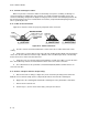
a. Attach a heat sink or clamp (see Figure A-5) on the lead of the part being removed from the
PCB; this ensures that the clamp (not the component) absorbs the heat from the soldering iron.
b. Apply heat to the soldering joint and hold the soldering iron on the joint until the solder melts.
c. Remove the desoldered end.
d. Perform steps a, b, and c for the other lead(s) of the part for removal.