
Users Manual
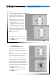
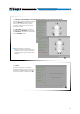
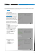
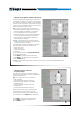
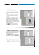

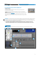
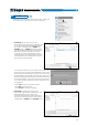
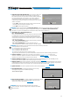
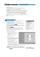
Table Of Contents
- Index
- 1. PRODUCT DESCRIPTION
- 2. PACKAGING CONTENTS
- 3. bit One HD Virtuoso AND DRC MP INSTALLATION
- 4. CONNECTION PANELS - DESCRIPTION
- 5. CONNECTIONS
- 6. bit One HD Virtuoso SOFTWARE AND DRIVERS - INSTALLATION GUIDE
- 7. bit One HD Virtuoso SETUP WITH PC
- 8. bit One HD Virtuoso SETUP USING A PC
- 9. TROUBLESHOOTING
- 10. TECHNICAL SPECIFICATIONS
- 11. ADDENDUM
45
USER'S MANUAL
If the system features ampliers provided with the
AD Link digital input and you want to connect them
to the system, you need to select them on this
setup procedure window.
The CH1-CH8 output channels will be available
on the AD LINK 1 socket, while the CH9-CH13
channels will be available on the AD LINK 2 socket.
5. Selection of the ampliers connected through
the AD Link / AC Link connection system.
4 Processor outputs
(Ch1÷Ch13 IIR MODE) allocation
The bit One HD Virtuoso features 13 output
channels. On this specic step of the procedure,
any signal can be assigned to each output
channel.
Eg.: the outputs 1 and 2 can be assigned to the
rear channels simply to avoid having to
lengthen the cables going to the specic
amplier.
For a matter of convenience, if the output 1 is
assigned to the left woofers, the software will
automatically assign the output 2 to the right
woofers. If during the procedure the output 1 is
assigned also to the left mid-high speakers, the
software will show a warning message. Change
the allocation of one of the two numbers marked
in red and the software will automatically select
the rst available channel.
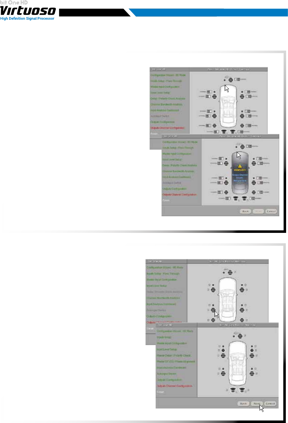
Press BACK to go back to the previous step.
Press NEXT to continue with the conguration.
Press CANCEL to exit.
Remark: remember to assign the corresponding
Amp ID to the specic amplier. The bit One HD
Virtuoso will automatically recognize the identied
amplier.
7