® ELECTRONICS CORP. XM® SATELLITE DIGITAL AUDIO RECEIVER SYSTEM MODEL SRXM-001 INSTALLATION MANUAL FOR USE WITH THE RADIO RECEIVER UNIT (RRU) MODEL XM-RCV F or C ustom er S ervice Vis it O ur W ebsite A t 999.audiovox.
INTRODUCTION The Audiovox Electronics XM® Satellite Digital Audio Control And Receiver System (Model SRXM-001) was developed to allow the user to listen to a huge selection of programming supplied by a subscription to XM® Radio. (XM®-compatible antenna also required).
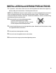
INSTALLATION and WIRING PRECAUTIONS 1. To prevent a short-circuit, Be sure to turn off the ignition and remove the negative (-) battery cable, prior to installation. Connect power wires last. NOTE: If the SRXM-001 System is to be installed in a car that is equipped with an on-board drive or navigation computer, do not disconnect the battery cable. If the cable is disconnected, the computer memory may be lost. Under these conditions, use extra caution during installation not to cause a short circuit. 2.
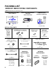
PACKING LIST SRXM-001 MAIN SYSTEM COMPONENTS (NOTE: Components are not drawn to scale.) SATELLITE SYSTEM CONTROL UNIT (SCU) Model # SAT-COM 4 7 2 3 5 6 8 9 SFT TO RRU L AUDIO OUT SAT. R L R TER. AUDIO OX TO SCU AUDIO OX SATELL ITE RADIO RF MODULATO R 0 DIN OUT 1 pc. TO RADIO ANT. 1 TO CAR ANT. AUDIO OX FM MODULATOR / CONTROL INTERFACE POWER RADIO RECEIVER UNIT (RRU) Model # XM-RCV 1 pc. (P/O SAT-COM) 1 pc.
R L AUDIO OUT DIN OUT AUDIO OX TO RADIO ANT. SATELLITE RADIO RF MODULATOR TO CAR ANT. R SAT. L TER. TO RRU NOTE: “C” Before routing the Din Cable to connect the FM Modulator to the RRU, observe the color code to avoid any unnecessary re-work. The Gray connector is matched to the FM Modulator and the Black connector is matched to the RRU. TO SCU POWER AUDIO OX NOTE: “B” RCA to RCA Cable (supplied with system) used to connect the RRU Audio Ouput to the RF Mododulator Audio Input.
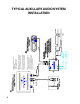
SAT. R L DIN OUT AUDIO OX TO CAR ANT. TO RADIO ANT. SATELLITE RADIO RF MODULATOR POWER TER. R NOTE: “C” Before routing the Din Cable to connect the FM Modulator to the RRU, observe the color code to avoid any unnecessary re-work. The Gray connector is matched to the FM Modulator and the Black connector is matched to the RRU. L AUDIO OUT TO RRU AUDIO OX TO SCU 6 NOTE: “B” RCA to RCA Cable (supplied with system) used to connect the RRU Audio Ouput to the Radio Reciever Auxilary Input.
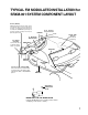
TYPICAL FM MODULATED INSTALLATION for SRXM-001 SYSTEM COMPONENT LAYOUT Ground (BLACK) Attach this wire to the chassis of the car. Be sure that the surface is free of paint and is not rusty. If a proper ground connection is not made, the SRXM-001 System may not operate correctly and stray noise may be picked up by the unit.
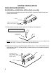
SYSTEM INSTALLATION RADIO RECEIVER UNIT (RRU) PROCEDURE for HORIZONTAL INSTALLATION of the RRU 1. Attach the mounting brackets to each side of the RRU, using the 4 Phillips Round Head Screws (4mm x 8mm). Bracket Phillips Head Screws (4mm x 8mm) used in 4 places 2. Determine the mounting location and drill 4x 1/8” (4mm) mounting holes. WARNING Never mount the unit near the fuel tank.
PROCEDURE for VERTICAL INSTALLATION of the RRU 1. Attach a mounting bracket to each side of the RRU, using the 4 Phillips Round Head Screws (4mm x 8mm). RRU Phillips Head Screws (4mm x 8mm) used in 4 places Bracket 2. Determine the mounting location and drill 4 x 1/8” (4mm) mounting holes. WARNING Never mount the unit near the fuel tank. 4x 1/8” (4mm) mounting holes Carpet NOTE: If mounting surface is carpeted, use caution when drilling holes to prevent drill bit from catching on carpet.
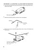
PROCEDURE for the MOUNTING of the RRU UNDER THE REAR DECK 1. Attach the mounting brackets to each side of the RRU, using the 4 Phillips Round Head Screws (4mm x 8mm). Bracket Phillips Head Screws used in 4 places (4mm x 8mm) 2. Determine the mounting location and drill four 4mm mounting holes. Underside of Rear Deck 4x 1/8” (4mm) mounting holes (4 places) 3. Mount the unit in place, using 4 Self-tapping Screws (5mm x 15mm), w/Flat Washers and Lock Washers.
INSTALLING THE SATELLITE SYSTEM CONTROL UNIT (SCU) PROCEDURE for a TYPICAL INSTALLATION of the SCU USING HOOK & LOOP ADHESIVE TAPE (SUPPLIED) 1. Determine where the SCU is to be located (flat surface) NOTE: The chosen position must allow a clear view of the display and easy access to the controls for both the Driver and Passenger of the vehicle. 2. Using an Alcohol Swab, clean and dry the entire surface area where the SCU is to be mounted and the back surface of the SCU. 3.
PROCEDURE FOR A TYPICAL BRACKET INSTALLATION OF THE SCU (Bracket not supplied) Audiovox suggests this type of installation over the Hook & Loop type of installation though the Hook & Loop installation (if done correctly) is a secure and sufficient mounting option. Installation of the SCU using a bracket results in a professional, factory-installed look, without visibly damaging the interior of the vehicle.