
Service manual

09/09 Rev. 5.02-02 SERVICE MANUAL Service Electronics
AP 4.4 – AP 5.4 – AP 7.t
7
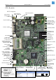
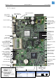
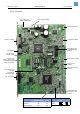
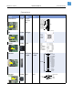
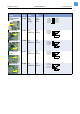
Display CN 503 JST
B24B-
PHDSS
JST
BHDR-
24VS
Peripherals motor
driver
CN 504 JST
B14B-
PHDSS
JST
PHDR-
14VS
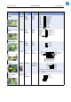
Stepper motor CN 601 JST
B04B-
XASK-1
JST
XAP-
04V-1
Power supply CN 701 JST
B9PS-VH
JST
VHR-9N
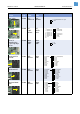
RS232 CN 801 DSub9-F DSub9-M
(1:1 cable to
the host)
Power supply
control
CN 802 JST
B4B-EH-A
Function /
Picture
Circ.
Diagr.
Type on
board
Type at
cable
Pin assignment on board
1- Key Prog/Esc
3- Key Feed
5- Key Cut
7- Key Online
9- E1 (CS1)
11- RS (A0)
13- R/ nW
15- LED Error
17- +5V
19- GND
21- GND
23- nReset
2- D0
4- D1
6- D2
8- D3
10- D4
12- D5
14- D6
16- D7
18- +5V
20- GND
22- E
24- E2 (CS2)
1- Motor CLK
3- Motor CW/CCW
5- PWM 7
7- Rewinder Cntrl
9- SCL
11- nMaster Reset
13- GND
2- Foilmotor CLK
4- GND
6- Perimotor CLK
8- GND
10- SDA
12- +5V
14- GND
1- Out 2B
2- Out 1B
3- Out 1A
4- Out 2A
5- GND
6- Motor Supply 45V
7- Motor Supply 45V
8- GND
9- GND
4- Power Fail
3- Temp. Sense
2- GND
1- +5V
5- GND
4- (DTR)
3- TxD
2- RxD
1- (CD)
9- (RI)
8- CTS
7- RTS
6- (DSR)
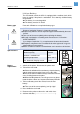
Pin 9 provides 5V/170mA, if JP801 is connected.
L CAUTION! Pin assignment looked at from „PC point of view“!
(Printer = DCE)
1- GND
2- SDA
3- SCL
4- Power Fail