
Service manual


09/09 Rev. 5.02-02 SERVICE MANUAL Service Electronics
AP 4.4 – AP 5.4 – AP 7.t
37
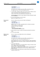
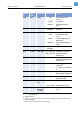
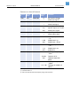
Sensors on the stepper motor output stage board
(AP7.t)
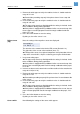
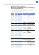
Sensors on the BLDC motor output stage board (AP5.4)
¯ Only valid for…
– „AP 5.4 peripheral with internal rewinder“, or
– „AP 5.4 basic“, with retrofitted internal rewinder,
– if the dispensing edge light barrier is connected to the BLDC output stage
board.
Sensor
#
Sensor
name
Connector # Typical value Condition
1.01 Option J4 -- Without function
1.02 Option J8 -- Without function
3.01 Headlift J4 <=10 Printhead sensor open
>=220 Printhead sensor
covered
3.02 Option J8 -- Without function
4.01 Peri. 1 J4 255 Light barrier covered
(TCS: Top blade at the
upper limit position)
<=10 Light barrier open
4.02 Peri. 2 J8 <=10 (TCS-) cover switch
closed and stacker not
full
255 (TCS-) cover switch open
or stacker full
[Tab. 11] Sensor test conditions for sensors, which are connected to the output stage board
(AP 7.t).
Sensor
#
Sensor
name
Connector # Typical
value
Condition
8.01 Rew.S. J4 0 Dispensing edge light barrier
open
255 Dispensing edge light barrier
covered
8.02 O Rew calculated
Value
0 Ø of the backing paper
rewinder roll is not known
ca. 35-
120
Ø of the backing paper
rewinder roll in milimeters
[Tab. 12] Sensor test conditions for sensors, which are connected to the BLDC motor output
stage board (AP 5.4).