
Service manual


09/09 Rev. 5.02-02 SERVICE MANUAL Service Electronics
AP 4.4 – AP 5.4 – AP 7.t
36
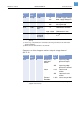
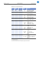
Sensors on the stepper motor output stage board
(AP5.4)
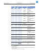
0.10 M-Supp CN 701 0 No motor supply voltage
255 Motor supply voltage o.k.
0.11 Start CN 803/804 0 Start signal low (IN1)
255 Start signal high
0.12 O Foil calculated
value
0 Foil diameter unknown
appr. 35-80 Foil diameter in mm
0.13 H (°C) Value
calculated
out of 0.07
appr. 25-70 Temperature at printhead
in °C
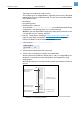
b)
a) Occurs e.g., if the printhead is connected to the wrong connector on the CPU board
(three possibilities).
b) Below 30°C the measurement is not accurate.
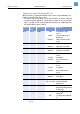
Sensor
#
Sensor
name
Connector
#
Periph. Typical
value
Condition
4.01 Peri. 1 J4 Dispensing
edge light
barrier
0 Dispensing edge
light barrier open
255 Dispensing edge
light barrier covered
Cutter <=10 Cutter in end
position
255 Cutter not in end
position
External
Rewinder
0…255 Dancer arm position
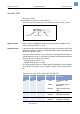
[Tab. 10] Sensor test conditions for sensors, which are connected to the output stage board
(stepper motor, AP 5.4).
Sensor
#
Sensor
name
Connector # Typical value Condition
[Tab. 9] (Cont.)Sensor test conditions for sensors, which are connected to the CPU board
(AP 7.t).