
Service manual

09/09 Rev. 5.02-02 SERVICE MANUAL Service Platinen
AP 4.4 – AP 5.4 – AP 7.t
3
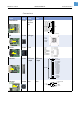
Feed motor (CN601)
Punch sensor (CN905)
Ribbon sensor
(CN906)
Pressure lever sensor
(CN907)
Reflex sensor
(optional) (CN908)
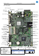
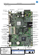
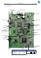
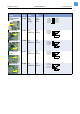
CPU Boards
AP5.4 Layout
Slot for CF card
(CN201)
RS-232 (CN801)
Centronics (CN501)
Keyboard (CN502)
Power supply (CN701)
Optional for extensions
Control lines to the
motor driver boards for
peripherals (Cutter, ext.
Rewinder, int.
Rewinder) (CN504)
Printhead Kyocera
KPA 104/KPA 106
(CN901)
Printhead Kyocera
KCE (CN902)
Printhead Rohm
KF2004/KF3004
(CN903)
USB (CN302)
JP501 (normal
operation: open!)
Ethernet 10/100 Base T
(CN401)
Ethernet status LED
JP502 (normal
operation: open!) Starts
micromonitor (internal
diagnostic software)
Control lines HME
power supply (2x I
2
C,
1x Power Fail, 1x GND)
(CN802)
Foot switch or stacker-
full-signal (CN803)
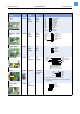
Function JP303 open (normal
operation)
JP303
closed
Boundary Scan On Off
Debug Port Off On
Signals I/O board On Off
5V supply for IC
controling the
dispensing edge
I/O board (RS-232/422/
485 I/O signals)
(CN804)
JTAG for Debugger
and Boundary Scan
(CN301)
LCD display (CN503)
RFID module or
internal scanner
(CN904)
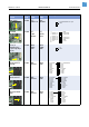
Jumper Boundary
Scan
Debug
JP301
JP302
Check LED motor
voltage, yellow (D20)
Check LEDs for core
voltages:
D10 red (left)
D11 green (right)
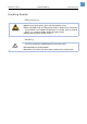
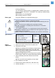
CAUTION! - Check the battery
regularly and replace it if
necessary!
WARNING! - Danger of
explosion, if the battery is
incorrectly replaced!!
AVERTISSEMENT! - Il y a un
danger d´explosion, si la batterie
est replacée
incorrectement!
Batterie for realtime clock
(Lithium 3V, CR2032)
JP801 - If connected, a
5V /170mA supply
voltage is provided at
the RS-232 connector
(CN801) at pin 9
(earliest with board
index -04)