
Service manual

09/09 Rev. 5.02-02 SERVICE MANUAL Service Electronics
AP 4.4 – AP 5.4 – AP 7.t
29
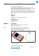
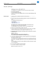
The left value is the control value for the LED current (Default: 128).
The right value is the sensor value read back (here: 6).
1. Turn the ribbon unwinding mandrel by hand and watch the read back value.
Sensor uncovered: the value should match the range 5..7.
Sensor covered: the value should match the range 220..255.
If the value doesn´t match this range: modify the control value by pressing the
Cut or Feed button.
2. Press the Online button to save the setting.
With this, the ribbon sensor is set.
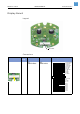
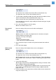
Pressure roll
switch
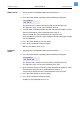
Next, the settings of the pressure roll switch are displayed:
¯ Because this is a switch, not a light barrier, the function can only be
checked. Settings are not possible.
Left value: 128 (stays unchanged)
Right value:
– 0 (Pressure roll lever open)
– 220…255 (Pressure roll lever locked)
3. Open and close the pressure roll lever by hand and watch the read back
value.
4. Press the Online button.
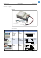
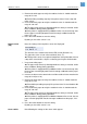
Reflex sensor
(bottom)
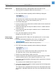
Next, the settings of the bottom reflex sensor are displayed:
The left value is the control value for the LED current (Default: 112).
The right value is the sensor value read back (here: 17).
¯ The bottom reflex sensor is an optional component. If the printer doesn't
have a bottom reflex sensor built in, skip this section by pressing the Online
button.
1. Insert some white paper.
¯ The paper stripe must be pulled tight while the setting is checked, similar
to the conditions during printing operation.
¯ If the printer is equipped with an additional reflex sensor on the top side,
the test paper must be light-proof! Put thick enough cardbord under the
paper, if it is not.
2. Increase or decrease the control value until the read back value matches the
range of 8..20 (best: 10).
Sensor Adjust
128 Foil 6
Sensor Adjust
128 Lever 236
Sensor Adjust
112 Reflex 17