
Service manual

09/09 Rev. 5.02-02 SERVICE MANUAL Service Electronics
AP 4.4 – AP 5.4 – AP 7.t
22
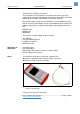
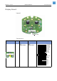
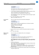
Display Board
Layout
Connectors
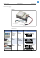
CPU board
Picture Circ.
Diagr.
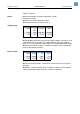
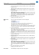
Type on board Type at cable Pin assignment on board
JST
B24B-PHDSS
JST
BHDR-24VS
24- E2 (CS2)
22 - E
20 - GND
18 - +5V
16 - D7
14 - D6
12 - D5
10 - D4
8- D3
6- D2
4- D1
2- D0
1- Key Prog/Esc
3- Key Feed
5- Key Cut
7- Key Online
9- E1 (CS1)
11- RS (A0)
13- R/ nW
15- LED Error
17 - +5V
19 - GND
21 - GND
23- nReset