
Service manual

09/09 Rev. 5.02-02 SERVICE MANUAL Service Electronics
AP 4.4 – AP 5.4 – AP 7.t
21
Testing the Signal Interface
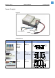
The USI-testbox was designed for use with the USI interface, the „big
brother“ of the I/O board, matching the 64-bit printer family. But it can also be
applied to the I/O board, if the following is taken into account:
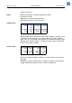
Not all of the output signals on the USI board are also available on the I/O
board. The pins of not available signals are grounded on the I/O board. The
following signal lamps for outputs are therefore always lighting on the test-
box:
• RIBBON OUT
• MEDIA OUT
• WARNING
Those inputs are not available on the I/O board:
• PLC ERROR
• TOUCH DOWN SENSOR
• HOME POS. ERROR
• MATERIAL LOW
Application of
the testbox
• Simulating inputs
• Checking outputs
• Monitoring of drive signals sent by the system control
• Aid for setting up the machine
Notes The polarity of the testbox is low-active, therefore rules:
¯ Inputs are pulled low when the push-button is pressed.
¯ Outputs are low, when the LED lights.
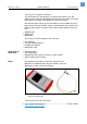
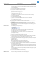
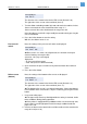
[3] Left side: The USI testbox (A2739). Right side: Connection cable (A2842). Both parts are
required for the application.
Testing the Serial Interface
P See parameter description of SERVICE FUNCTION > Com2 port test in topic section
Info-Printouts & Parameters
.