
Service manual


09/09 Rev. 5.02-02 SERVICE MANUAL Service Electronics
AP 4.4 – AP 5.4 – AP 7.t
19
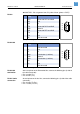
Input/Output Signals
Internal supply The I/O board provides a galvanically decoupled 5 V source. External elec-
tronics, powered from this source, must not consume more than 0.5W (5 V /
100 mA).
¯ Maximum admissible output current: 100 mA
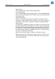
External supply The I/O board outputs may be powered by an external source from 5V to
24 V (pin 7). External electronics, powered from this source, must not consu-
me more than 200 mA per output channel.
¯ Maximum admissible output current: 200 mA
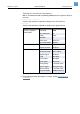
Fuses The fuses used on the I/O board are polymeric positive temperature coef-
ficient resistors. If they trip, they don´t blow and after cooling down, they work
again. They don´t need to be replaced.
Input signals
• START PRINT
• FEED
• PAUSE (optional: APSF)
• REPRINT
P For details see topic section Info-printouts & Parameters.
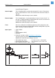
The input signals are powered by an internal 5 V source.
¯ Maximum admissible input voltages: 0 to 24V
• Active (low) input signal: V
IL
= 0 to 1 V at I
IL
≈ 10 to 20 mA
• Inactive (high) input signal: V
IH
= 40 to 24 V at I
IH
≈ 0 to 1 mA
• Max. frequency for APSF signal: 10 kHz
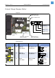
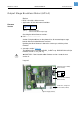
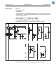
[1] I/O board: Input circuitry and possible connections to external electronics.
DC/DC
5V
IN
GND
5V..24V
5V