
Service manual


09/09 Rev. 5.02-02 SERVICE MANUAL Service Electronics
AP 4.4 – AP 5.4 – AP 7.t
16
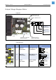
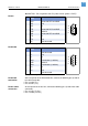
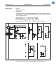
¯ CAUTION - Pin assignment from „PC point of view“ (printer = DCE)!
RS 232
RS 422/485
RS 422/485
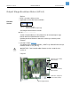
termination
At the last printer at the RS 422/485 line, connect the following pins (inside of
the cable connector):
• Pins 3 and 4 (Tx-)
• Pins 6 and 7 (Tx+)
RS 485 2-wire
connection
At each printer on the bus line, connect the following pins (inside of the cable
connector):
• Pins 2 and 3 (Tx-/Rx-)
• Pins 7 and 8 (Tx+/Rx-)
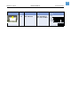
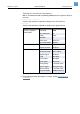
Pin Signal name
(host)
Signal direction from I/O board
1 DCD Short with DTR and DSR
2 RxD Out
3TxD In
4 DTR Short with DCD and DSR
5 GND Ground
6 DSR Short with DTR and DCD
7RTS In
8 CTS Out
9 (RI) Not connected
[Tab. 3] Pin assignment RS 232 connector
5
9
8
7
6
4
3
2
1
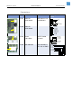
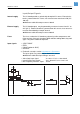
Pin Signal name
(host)
Signal direction from I/O board
1 Not connected
2 Rx- Out
3Tx- In
4 Term. Termination (110 Ohm)
5 GND Ground
6 Term. Termination (110 Ohm)
7Tx+ In
8 Rx+ Out
9 Not connected
[Tab. 4] Pin assignment RS 422/485 connector
5
9
8
7
6
4
3
2
1