
Instruction manual

– 9 –
h DC Input Connector Protective Cap
This is the protective cap for the DC input connector. It is re-
moved to enable the plug of the PB-701 power Supply to be
inserted into the connector.
When the PB-701 is not being used, it is always important to
replace this cap to prevent dust entering the unit. For details on
the power supply, refer to Section 4, Power Supply Connection.
i Output Connector Protective Cap
This is the protective cap for the output connector. When output
is not required, it is always important to cover the connector with
the protective cap to prevent dust from entering the unit.
A serial output representing the displayed value is available at
this connector. Before making a connection, always switch the
power supply off. For details on the seral output, refer to Section
10, Serial Output Specifications.
By inserting the connector from the RQ-2110 Function Printer
(option) into this connector, it is possible to create a printout of
not only measured values but to perform statistical calculations
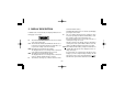
e Inch/mm Switch
This switch selects either “inch” or “mm” as the units for display
of the measured value. The units are alternately selected each
time the switch is pressed. The selected mode is maintained even
when the power is switched off.
The “in” and “mm” annunciators will appear in the display to indi-
cate the selected unit.
Note that it is also possible to press the switch after a measure-
ment has been made to convert the units indicated in the dis-
play.
f Display
This (LCD) liquid crystal display indicates the measured value
and includes a sign. For details, refer to Section 5 describing the
display.
g Spindle Cap