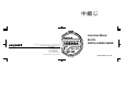
中綴じ Instruction Manual EG-225 DIGITAL LINEAR GAUGE *Outer appearance and specifications are subject to change without prior notice. HOME PAGE: http://www.onosokki.co.jp/English/english.htm WORLDWIDE ONO SOKKI CO., LTD. 3-9-3 Shin-Yokohama, Kohoku-ku, Yokohama 222-8507, Japan Phone : +81-45-476-9712 Fax : +81-45-470-7244 E-mail : overseas@onosokki.co.jp in/ mm MODE POWER RESET +/- B00000278/IM89013101(4) 102(MS)02K ONO SOKKI CO., LTD.
Warranty 1. This product is covered by a warranty for a period of one year from the date of purchase. 2. This warranty covers free-of-charge repair for defects judged to be the responsibility of the manufacturer, i.e., defects occurred while the product is used under normal operating conditions according to descriptions in this manual and notices on the unit label. 3. For free-of-charge repair, contact either your sales representative or our sales office nearby. 4.
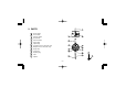
中綴じ INTRODUCTION CAUTION Your new EG-225 Digital Linear Gauge has passed a strict quality control program. To ensure that you get the most out of your new instrument, we strongly recommend that you read and follow this instruction manual. The EG-225 Digital Linear Gauge consists of the following parts. The rubber o-ring mounted on the spindle serves as a stopper for the spindle. Do not attempt use of the gage with this o-ring removed, as this can cause failures.
Before Using this Gauge • Before using the EG-225, remove the rubber ring which is used to hold the spindle in place. • Over-discharge can occur during shipment. If the EG-225 is to be used with both battery and AC power, first charge the battery sufficiently. (The recharging method is described in Section 4, power supply connection.) • When using the EG-225 for the first time, press the power switch and reset switch simultaneously to perform a system reset.
TABLE OF CONTENTS 1. 2. 3. 4. 5. 6. 7. 8. 9. 10. 11. 12. Page FEATURES .................................................................................................................... 4 PARTS ........................................................................................................................... 6 FUNCTIONAL DESCRIPTION ...................................................................................... 7 POWER SUPPLY CONNECTION .....................................................
1. FEATURES The EG-225 compact digital linear gauge conforms to AGD Group II mechanical specifications. Its excellent response enables spindle travel up to 20 in/s (500 mm/s). With a resolution of 0.00005, it is possible to make measurements with a stroke of 1 inch. Three measurement functions (normal, absolute zero, and preset) are available for selection, depending upon the particular application. In addition, it features selection of either English or metric readout and has a serial data output.
In addition compatible with all major SPC systems • Data-Myte • OS Gage talker • Verax • QMS Genesis • Dataputer –5–
2.
3. FUNCTIONAL DESCRIPTION First, we will describe the functions of each part, as used in the normal basic measurement function. Of the EG-225 parts, the operation in the absolute zero or preset function will be noted only when it is different from operation in the normal function. a Power Switch When the power switch is pressed, the EG-225 is powered and measurement is possible. When this is done, the LCD display reads “0”.
then the (R) range (maximum to minimum) display mode, and finally back to the normal measurement mode. (1) In the normal measurement mode, the measured value is continuously displayed. (2) If the mode switch is pressed one (within two seconds), “MAX” appears in the display, indicating that the maximum value display mode has been reached. In this mode, read-in measured values are continuously compared and the maximum value measured is displayed.
e Inch/mm Switch h DC Input Connector Protective Cap This switch selects either “inch” or “mm” as the units for display of the measured value. The units are alternately selected each time the switch is pressed. The selected mode is maintained even when the power is switched off. The “in” and “mm” annunciators will appear in the display to indicate the selected unit. Note that it is also possible to press the switch after a measurement has been made to convert the units indicated in the display.
and recording of outputs as well. Using the optional BH-100 Interface Unit, any computer which is equipped with RS-232C interface can be used (with user application software) to perform such functions as editing and calculation on measured values. j Finger Lifter If the normal function is set, and the RESET switch is pressed for more than two seconds and released, the display will indicate “AB”, indicating that the absolute zero function has been selected.
MIN mode will be the preset value and, in the R mode, the preset value will be zero. (2) If the RESET switch is pressed for more than two seconds and released, return is made to the normal function. After this, if the switch is pressed further, the absolute zero function will be selected. 3. Mode Switch In this function, mode switching is not possible (i.e., it is protected). 2.
4. Inch/mm switch In this function, it is not possible to perform inch mm switching. In this function, the unit is fixed at the position selected in the normal function. In this function, it is not possible to perform inch/mm switching. In this function, the unit is fixed at the position selected in the normal function.
4. POWER SUPPLY CONNECTION (2) Battery Operation (1) PB-701 Power Supply Remove the protective cap from the round connector hole at the top of the gauge and insert the plug of the PB-701 into this connector. By connecting the PB-701 in this manner, the unit operates from AC line power. Cord length:5.9ft Note 1. When the PB-701 is not being used, always be sure to replace the protective cap to prevent dust from entering the gauge. 2. If the self-contained rechargeable battery is completely discharged (i.
5. DISPLAY DESCRIPTION In addition to the measured value, the display indicates the following types of messages. in: This annunciator indicates that inches have been selected as the measurement unit. mm: This annunciator indicates that millimeters have been selected as the measurement unit. These annunciators correspond to the setting of the inch/mm switch. MAX: This indicates the maximum value display.
Switch power ON once again, “B” will appear for approximately two seconds, after which the power will be switched off automatically. : This indicates the counting direction. : Addition (+ direction) when spindle is pushed in. : Subtraction (– direction) when spindle is pushed in. +: This indicates that the measured value is positive. For negative value, “–” will appear in the display and for a measured value of 0, no sign is indicated. AB: This indicates that the absolute zero function has been selected.
6. OPERATION DESCRIPTION As long as the system reset is not performed, the following three parameters will be held in memory even with the power switched off. 1. inch mm selection 2. Preset setting value 3. / direction When the power is switched ON, the normal function will be selected automatically. This normal function is used as the basis for switching to the absolute zero function or preset function. (1) Normal function The normal function is the basic measurement function.
display is blank, and changes to “0” when the display changes to “0”. If “E” appears in the display during a measurement, set the power to OFF as would be done for the normal measurement mode. (2) Absolute Zero Function (3) Preset Function The spindle position when the power is switched ON is taken at the absolute zero point, and the absolute zero function keeps constant track of the displacement from this position, displaying the difference.
lease it to set the offset value at the instant the switch is released. The preset value setting procedure is noted below (Preset Value Setting Procedure). If “E” appears during measurement, perform a reset by switching the power off. By pressing the mode switch (for less than two seconds) it is possible to switch through the sequence NORMAL → MAX → MIN → R, after which return is made to the normal mode.
When the digit to be set is flashing, release the mode switch. At this point, if the MODE switch is pressed for less than two seconds, each time it is pressed the digit value will change sequentially from 1 through 0 and return to 1. However, if the inch unit is selected in the preset function, the final digit is limited to a value of 0 or 5. When the setting of the final digit is completed, “P” only flashes in the display.
(2) Lug Mounting 7. MOUNTING METHOD (1) Mounting By Grasping the Stem The diameter of the stem is 0.375/0.374”, enabling mounting on either an optional gauge stand (ST-022, ST-044B with option) or a stand which has been prepared by the user as shown in the figure below. 0.376/0.375"DIA Pass a bolt through the lug mounting hole (0.25” diameter) on the rear cover and tighten securely.
8. CONNECTION OF THE FINGER LIFTER 9. OPERATING PRECAUTIONS The finger lifter can be inserted between the lift screw and the spindle by removing the contact tip at the end of the spindle as shown in the figure below. (1) When mounting to a fixture, always be sure that the mounting is made so that the direction of spindle movement and the long direction of the object being measured agree and that the spindle makes contact at the proper position.
(2) Replacement of Contact Tip When replacing the contact tip, hold the spindle firmly using a rubber band or similar material. Spindle Rubber band (3) Lowering and raising of the spindle should be performed by the AA-970 accessory finger lifter or the optional AA-971 Top Lifter. (4) Care should be taken not to TOUCH the spindle with the hands as dirt on the spindle can impair smooth movement. If dirt has accumulated on the spindle, wipe it off with a cloth dampened with alcohol.
10. SPECIFICATIONS Measuring range ................... 1 in. (25.4mm) Resolution ............................. 0.00005 in. (1µm) Accuracy at 68°F (20°C) ....... 0.00012 in. (3µm) Response Speed .................. 20 in/s (500 mm/s) Display .................................. 6 digit LCD with sign Measuring Force ................... 0.33 lb [1.47N (150gf)] Power supply .........................
SERIAL OUTPUT SIGNAL SPECIFICATIONS 2. Output signal Electrical Characteristics 1. Connector Pin Arrangement All signals are output CMOS devices (1 LSTTL load drive capacity). HIGH ........ VOH>4.OV(VCC=4.5V, IOH=–10µA) LOW ......... VOH<0.4V(VCC=4.5V, IOL=1.
(3) Data: As shown in the table below, data consists of 12 steps which represents one value, each step consisting of four bits, output in the sequence 23 → 20.
Step 10 11 12 Name Unit Not use MAX MIN END 23 0 0 0 0 0 0 0 22 0 0 0 0 1 1 1 X 21 0 0 1 1 0 0 1 20 0 1 0 1 0 1 0 Max. 0 0 0 Min.
(4) RESET: Reset function can be externally controlled by inputing a low-level signal to the output connector pin No.4. 4. Timing Diagram 5V 0V 5V 0V V OH V OL Min 30 ms RESET button ON CK1 CK2 CK3 CK4 CK1 CK2 CK3 CK4 CK1 CK2 CK3 CK4 Step 1 (5) MODE: Mode function can be externally controled by inputing a low-level signal to the output connector pin No.5. V OH V OL Min 30 ms MODE button ON – 27 – Step 12 data (Approx 1.
11. OVERALL VIEW 1.988 CORD LENGTH:5.9ft DATA OUT 1.299 0.750 DC IN 0.394DIA. 0.256 1.614 2.362 2.5 1.378 0.413 WITH FINGER LIFT 1.122 1.122 0.197DIA. 0.827 0.375DIA. 1.063 0.785 0.624 1.785 0.039 0.25 +/- 3.262 RESET 0.098 MODE 0.250 1.313 2.165DIA. in/ mm POWER 0. 25 DI A. 2.047DIA.
中綴じ Instruction Manual EG-225 DIGITAL LINEAR GAUGE *Outer appearance and specifications are subject to change without prior notice. HOME PAGE: http://www.onosokki.co.jp/English/english.htm WORLDWIDE ONO SOKKI CO., LTD. 3-9-3 Shin-Yokohama, Kohoku-ku, Yokohama 222-8507, Japan Phone : +81-45-476-9712 Fax : +81-45-470-7244 E-mail : overseas@onosokki.co.jp in/ mm MODE POWER RESET +/- B00000278/IM89013101(4) 102(MS)02K ONO SOKKI CO., LTD.