
Owner's Manual


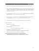


Table Of Contents
- Installation Guide
- Table of Contents
- Supplied Accessories
- Installation
- Tools Required / Preparation
- Installing the Snap-On Shroud
- Installing the Snap-On Screen Cover
- Installing the Trim Ring
- General Vehicle Installation Approach
- Vehicle Preparation
- Connecting the Dome Lights
- Installing the Mounting Bracket
- Wiring Diagram
- Mounting the Unit
- Removing the Screen Back Cover
- Removing the Trim Ring and Shroud
- Installing the Optional Thick Trim Ring
- Installing the Optional SmartStream Module (WM1)
- Troubleshooting
- Owners Manual
- Warranty

18
Installing the Unit Video System-Wiring Diagram
Wiring Diagram
6 Pin Power/Dome Light Harness
(P/N 112-4270)
WM1(Optional)
RF OUTPUT
HDH12(Optional)
5 Pin AV Output Harness
(P/N 112-4260)
5 Pin AV Input Harness
(P/N 112-4259)
1
1
24
2
5
9
0
1
1
2
4
2
6
0
0
NOTE: The Hidden 24 Pin connector only allows connection of either optional
SmartStream Module (WM1) or HD/USB Extension harness (HDH12).