
Owner's Manual


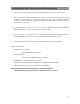


Table Of Contents
- Installation Guide
- Table of Contents
- Supplied Accessories
- Installation
- Tools Required / Preparation
- Installing the Snap-On Shroud
- Installing the Snap-On Screen Cover
- Installing the Trim Ring
- General Vehicle Installation Approach
- Vehicle Preparation
- Connecting the Dome Lights
- Installing the Mounting Bracket
- Wiring Diagram
- Mounting the Unit
- Removing the Screen Back Cover
- Removing the Trim Ring and Shroud
- Installing the Optional Thick Trim Ring
- Installing the Optional SmartStream Module (WM1)
- Troubleshooting
- Owners Manual
- Warranty

11
Installing the Trim Ring
The trim ring is attached to the video monitor using the perimeter screw bosses. It is
important that the screws used in this installation are not over tightened, and that the
video monitor and trim ring are mounted in such a way that the assembly does not distort
(or bend) when the mounting screws are tightened.
There are two Trim Ring options for mounting the Unit, one is to use the supplied Trim Ring
for all vehicles with at headliner mounting areas (no contour) or a thick Trim Ring (not
supplied) that can be cut to t the contour of a headliner that is not at (see Appendix B
of this manual).
NOTE: The trim rings supplied with this unit are not designed to be trimmed.
Installing the Trim Ring
1. Turn the DVD Player over on a surface with protective covering to prevent scratches.
2. Place the trim ring onto the DVD Player. Align the pins on the trim ring with the holes
in the metal chassis plate.
3. Locate the eight (8) M3 x 5mm screws in the hardware kit.
4. Using a screwdriver, install the eight (8) M3 x 5mm screws into the locations marked “A”
shown in the gure below.
NOTE: Use caution tightening screws as the threads may strip in the overhead assembly.
Trim Ring
DVD
Player
Trim Ring
on DVD
Player
(A)
(A)
(A)
(A)
(A)
(A)
(A)
(A)
TRIM RING SCREW
(A) M3 X 5mm Screw
(QTY 8)