MTG10UHD/MTG13UHD 10.1” /13.
Important Notices Installation of overhead products requires careful planning and preparation. Be extremely careful when working on a vehicle with side curtain air bags. Do not route wires near any portion of the side curtain air bag assemblies. This includes any anchor points in A, B, C or D pillars of the vehicle. Routing wires in these areas or running wires by the side curtain air bags can prevent the side curtain air bag from fully deploying which can result in personal injury to vehicle occupants.
Safety Precaution For safety reasons, when changing video media, it is recommended that the vehicle is not in motion, and that you do not allow children to unfasten seat belts to change video media or make any adjustments to the system. System adjustments can be accomplished using the remote control, while seat belts remain fastened. Enjoy your entertainment system but remember the safety of all passengers remains the number one priority.
Table Of Contents Materials Include In This Package.............................................................6 Installing The Unit In A Vehicle .................................................................. 8 Installing The Snap-On Shroud ................................................................ 9 Installing The Snap-On Screen Cover....................................................10 Installing The Trim Ring ..............................................................................
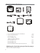
Materials Included In This Package 1 2 3 4 9 1 1 2 4 2 5 0 5 7 9 10 6 00 1 1 2 4 2 6 8 11 1. 10.1” / 13.3” TFT LCD Overhead Monitor with DVD Player 2.
Materials Included In This Package 3. Remote Control w/ Battery (P/N 500-003) - (1 pc) 4. For 10.1”-Mounting Bracket (P/N 201-413) 13.3”-Mounting Bracket (P/N 201-414) - (1 pc) - (1 pc) 5. 6 Pin Power/Dome Light Harness (P/N 112-4270) - (1 pc) 6. AUX Pigtail (P/N 112B3227) - (1 pc) 7. 5 Pin AV input Harness (P/N 112-4259) - (1 pc) 8. 5 Pin AV output Harness (P/N 112-4260) - (1 pc) 9. For 10.
Installing the Unit In A Vehicle Tools Required 1. #2 Phillips Screwdriver 2. #1 Phillips Screwdriver 3. Utility or Razor Knife 4. Wire Strippers 5. Upholstery hook tool (for removal of panels as necessary) 6. Electrical Tape 7. Masking Tape 8. Multimeter to verify 12 volt DC and continuity (Do not use a test light or logic probe) 9. Marker pen – to mark headliner, to mark trim ring if used 10. Scribe (to mark trim ring if used) 11.
Installing the snap-on shroud Installing the Shroud *NOTE: Work on a soft surface to avoid damaging the plastic. 1. Remove the double sided tape backing from the two strips on the center section of the shroud. 2. Hook the shroud over the dome light and align the shroud tabs (1)with the eight openings around the rim of DVD player(2 ). 3. Slide the shroud down until the shroud completely covers the DVD player and that all eight tabs snap into all eight openings around the DVD player (1)& ,(2). 4.
Installing the Snap-On Screen Cover Installing the Screen Cover 1. Open the LCD screen. 2. Hook the two tabs “A” (as shown) on the bottom edge of the screen. 3. Carefully snap the opposite side over the hinge. NOTE: If the wrong color Shroud and Screen Cover is installed, refer to Appendix A of this manual for instructions to change the Shroud and Screen Cover color.
Installing the Trim Ring The trim ring is attached to the video monitor using the perimeter screw bosses. It is important that the screws used in this installation are not over tightened, and that the video monitor and trim ring are mounted in such a way that the assembly does not distort (or bend) when the mounting screws are tightened.
General Vehicle Installation Approach 1. Decide upon system configuration and configuration and peripheral options that will be installed (ie...External Video Gaming System). 2. Review all manuals to become familiar with electrical requirements and connections. 3. Decide upon mounting locations of all components and method of mounting. 4.
Vehicle Preparation 1. Locate an accessory +12v power source with a good ground. These wires can be found at the ignition switch or fuse-box. Power Source t +12v when the key is in the ACC and run positions. t 0v when the key is OFF. NOTE: Always fuse the ACC +12V at the source where it is connected to the vehicle. 2. Some vehicles come equipped with a factory option that places the vehicle in an “Environmental Friendly” mode that shuts down the engine when the vehicle is not in motion.
Connecting the Dome Lights The dome lights in the video monitor require three connections to the vehicle’s wiring. There are two common types of dome light circuits used, positive switched systems or negative switched systems. Positive switched systems supply voltage to the interior lights to turn ON; negative switched systems apply ground to illuminate the bulbs.
Connecting the Dome Lights Positive Switched Dome Lighting To 3 pin connector on Monitor Red/Black-Lamp ON Black/Red-Lamp Common Purple/Brown-Lamp Auto To constant +12 VDC Fused Factory Dome Light Circuit To constant +12 VDC Factory Door Ajar Switch or Body Control Computer Negative Switched Dome Lighting To 3 pin connector Red/Black-Lamp on Black/Red-Lamp common Purple/Brown-Lamp Auto To constant +12 VDC Fused To constant +12 VDC Factory Door Ajar Switch or Body Control Computer 15
Installing the Mounting Bracket Installing the Mounting Bracket 1. Once all the pre-wiring is complete, locate: t Mounting Bracket t (4) #8 x 3/8” Self-Drilling Screws 2. Carefully align the Mounting Bracket in the location it is to be installed with direction arrow facing the front of the vehicle (make sure there is nothing between the Mounting Bracket and Roof Cross-Member). NOTE: The headliner may need to be cut to install the bracket.
Installing the Unit Video System-Wiring Diagram 1. Connect the 6 pin harness to the unit and make the connections to the vehicle. 2. Connect the red and black power wires of the Power Harness to vehicle’s electrical system by connecting into an accessory hot line and a good ground.Soldering all power connection is the suggested technique that should be used to ensure a problem free connection. 3.
Installing the Unit Video System-Wiring Diagram Wiring Diagram RF OUTPUT WM1(Optional) HDH12(Optional) 6 Pin Power/Dome Light Harness (P/N 112-4270) 5 Pin AV Input Harness (P/N 112-4259) 9 1 1 2 4 2 5 0 5 Pin AV Output Harness (P/N 112-4260) 6 00 1 1 2 4 2 NOTE: The Hidden 24 Pin connector only allows connection of either optional SmartStream Module (WM1) or HD/USB Extension harness (HDH12).
Installing the Unit Video System-Mounting the Unit Installing the System 1. Make all electrical connections. 2. Attach the Unit to the mounting bracket using four M5 screws. CAUTION: The M5 screws are supplied in three different lengths (10mm, 20mm and 40mm) to facilitate proper installation. Use extreme caution when using these screws to avoid damage to vehicle roof or other components, wiring, etc.
Appendix A - Removing the Screen Back Cover This section is intended for situations where the color of the Shroud, Screen Cover and Trim Ring need to be changed after the unit is setup for installation. NOTE: Work on a soft surface to avoid damaging the plastic. Removing the Screen Back Cover 1. Starting from the back of the unit, carefully insert the supplied pry tool between the Housing and Screen Back Cover 2. Press the pry tool to release the Screen Back Cover. 3.
Appendix A - Removing the Trim Ring and Shroud Removing the Trim Ring 1. Remove the Trim Ring screws ((8) M3 x 5mm screws). NOTE: Do not Discard Screws! These screws are used to attach the new Trim Ring. 2. Remove the Trim Ring and discard. (8) (1) (7) (2) TRIM RING SCREW (8) M3 X 5mm Screws (6) (3) (5) (4) Removing the Shroud 1. Using the supplied pry tool, remove the slide knob from the dome light switch located on the side of the DVD player. NOTE: Do not Discard knob! The knob is reused. 2.
Appendix B - Installing the Optional Thick Trim Ring This section covers only special installation considerations for the optional thick trim ring installation. consideration for when an installation requires use of our Optional thick trim ring. Important NOTES before installing the thick trim ring: t There should be a gap between the headliner and the outer flange of the video monitor. 1. 2. Apply masking tape to the outside of the thick trim ring.
Appendix C - Installing the Optional SmartStream Module (WM1) This section is intended as an installation guide to connect the WM1 Module to the Unit NOTE: The WM1 Module is sold separately and is supplied with its own instruction manual. Installing the WM1 Module 1. Turn the DVD Player over on a surface with protective covering to prevent scratches. 2. Begin looping the excess WM1 Module harness under the protective top plate towards the back of the DVD player as shown. 3.
Troubleshooting SYMPTOM: REMEDY: No power at video monitor t Verify +12 VDC on the Red wire at 6 Pin Power/ Dome Light Harness behind the video monitor. Verify a ground connection with a continuity test from a known good ground to the black wire. Power but no video or sound t Verify that the Source is on and playing back compatible media content. Disc will not play or wrong region is displayed t Check to ensure the disc was put in with the correct side for playback (Label side up/shiny side down).
Troubleshooting SYMPTOM: FM Transmitter does not work REMEDY: t Check if radio is ON and in FM mode. t Check that radio is tuned to the same frequency as the unit is set to. t Select another FM channel. t Reposition the Unit Wireless FM antenna for better reception. Optional Module FMDIRB will allow the internal FM Transmitter to become a hardwired FM modulator. This option will provide the best FM connection to the vehicle radio. t Check if the battery is installed correctly.
www.voxxelectronics.com © 2016 Voxx Electronics Corp.
MTG10UHD/MTG13UHD 10.1” /13.
Warnings Do not use any solvents or cleaning materials when cleaning the video monitor. Do not use any abrasive cleaners, they may scratch the screen. Use only a lightly dampened lint free cloth to wipe the screen if it is dirty. Lock the LCD screen in the fully closed position when not in use. Before putting on headphones always adjust the volume setting to the lowest position.
Congratulations Congratulations on your purchase of DVD Player with drop-down video / monitor. The MTG10UHD/MTG13UHD has been designed to provide passengers with unlimited content options delivering smiles for many miles. Please read the directions that follow to familiarize yourself with the product to ensure that you obtain the best results from your equipment.
Table of Contents Features .............................................................................................................6 Controls and indicators diagram(front view) ....................................... 7 Controls and indicators diagram(side view) ......................................... 9 Remote Control Operation .......................................................................10 Remote Control functions .........................................................................
Features t w w %JHJUBM 5IJO 'JMN 5SBOTJTUPS 5'5 "DUJWF .BUSJY -JRVJE $SZTUBM %JTQMBZ LED Backlit Monitor t #VJMU JO %7% 1MBZFS t -BTU QPTJUJPO NFNPSZ GPS %7% 1MBZFS t 4JY "VEJP 7JEFP 4PVSDF *OQVUT DVD, USB, AV, AUX, HDMI/MHL 1, HDMI/MHL or SmartStream. t 64# 1PSU 6TFS "DDFTTJCMF XJUI .FEJB 1MBZCBDL BOE $IBSHJOH TVQQPSU t )% *OQVU 6TFS "DDFTTJCMF XJUI .)- TVQQPSU t )% *OQVU )JEEFO *OQVU WJB 1JO $POOFDUPS .
Controls and indicators diagram (front view) 1. POWER/SOURCE ( ) Button This button is used to turn the system on/off and to selcet the source . 2. Play/Pause (X/II ) Button This button is used to start playback of a disc or pause a disc. 3. DOWN / Previous ( ) Button Short press to select the source mode and system menu pages. Long press to select previous chapter or track during play the DVD. 4. MENU Select Button This button is used to display and select options on the system menu. 5.
Controls and indicators diagram (front view)-Continued 6. STOP () Button -Press the STOP button once: Stops playback. -Pressing the PLAY button again will resume normal playback from where movie was stopped. -Press the STOP button twice and then press the PLAY button to start playback from the beginning of the DVD. 7. EJECT ( ) Button This button is used for ejecting a disc from the disc compartment. 8. Dome Lights Provide additional interior illumination. 9.
Controls and indicators diagram (side view) 1. DVD Disc Insertion Slot For loading and removing discs. When a disc is inserted, the unit will automatically turn ON and switch to DVD source. Insert a disc with label side facing up. Note: The disc slot indicator is red when a disc is inserted and green when the disc slot is empty. 2. AUX IN 5IJT KBDL JT VTFE UP TVQQMZ FYUFSOBM BVEJP BOE WJEFP JOQVUT UP UIF VOJU 3. USB INPUT For connection of a USB memory device.
Remote control operation Battery Replacement 1. Remove the battery cover. 2. Insert two AAA batteries into the battery holder. Be sure to observe the correct polarity. 3. 10 Reinstall the battery cover into the battery holder until the holder is click .
Remote Control functions 1 32 2 31 3 30 4 5 CD CD CD CD CD CD 0 CD CD 29 6 ? - - - -+-+- + 8 9 10 11 12 13 14 15 16 17 18 19 20 21 28 27 GJ 0 VOL 26 25 24 23 22 11
Remote Control functions(Continued) * Function control is available on the unit and the Remote Control. ** Function not available in this model. 1. POWER* Press this button to turn the unit ON and OFF. 2. SOURCE* Press to display the Source OSD for DVD, USB, AV, AUX,HDMI1 and HDMI2. 3. DVD Source** No function on this model. 4. DVD Mode Select Button Switches certain function keys on the remote control for DVD function. 5.
Remote Control functions(Continued) 13. SCAN BACKWARD ( ) Press to search in a backward direction. Press repeatedly to change the search speed from UJNFT BOE OPSNBM TQFFE 14. SCAN FORWARD ( ) Press to search in a forward direction. Press repeatedly to change the search speed from 2, UJNFT BOE OPSNBM TQFFE 15. PREVIOUS ( ) Press to return to the previous chapter or track. 16. NEXT ( ) 1SFTT UP TLJQ UP UIF OFYU DIBQUFS PS USBDL 17.
Remote Control functions(Continued) 22. FM MODULATOR CHANNEL SELECT (C)** No function on this model. User may use the system menu to select the FM Modulator. 23. FMM ON/OFF Turns the FM Modulator power on/off. 24. AUDIO Press to display and select audio language in DVD mode. Each time this button is pressed, the language changes. 25. PIX ( Picture Select )** No function on this model. 26. VOLUME DOWN (-) or UP (+)** No function on this model. 27. STOP ()* Press to stop playback.
Turning the unit on or off 1. Push in the Screen Release button to unlock the LCD screen. The screen will drop down slightly. 2. Pivot the screen downward until a comfortable viewing angle is reached. The hinge friction will hold the screen in position while the system is in use. 3. Press the power button on the unit or the remote control to turn the system on and off. When in use, the internal backlighting will illuminate the controls.
Source menu 5IF 4ZTUFN JT DBQBCMF PG BDDFTTJOH TJY TPVSDF JOQVUT 5P TFMFDU PS DIBOHF B TPVSDF QSFTT UIF source button on the front panel or the Source button on the remote control. The source OSD will appear on the screen as shown in the figure below. Use the + or - cursor buttons on the front panel or the S or T cursor buttons on the remote control to highlight a source. Press the Source button on the front panel or the OK button on the remote control to select the desired source.
Source menu(Continued) HDMI 1 & HDMI 2 These Source inputs allow the user to enjoy high-definition digital images and high-quality sound by connecting a HD device such as a Blu-ray player or smartphone with an HDMI output to the system. The HDMI inputs also allow the user to connect with a Mobile High-Definition Link (MHL) mobile phone. Connect your HDMI/MHL device with an optional HDMI cable. Smartphones and Tablet require the appropriate adapter for your smart device.
System Menu Setting and Adjustments The Setup Menu contains features and options that let you customize your DVD player. 'PS FYBNQMF ZPV DBO TFU B MBOHVBHF GPS UIF PO TDSFFO EJTQMBZ PS TFU VQ 1"3&/5"- controls to control DVD playback for children. Using the System Menu 1. Press the System Menu button on the remote. The System Menu appears on the screen as shown in the figure below.
System Menu Setting and Adjustments(Continued) 7. If without a Remote control user can use the local key to select the function setting. B .FOV -POH QSFTT UP DBMM VQ UIF TFUVQ NFOV TDSFFO JOGPSNBUJPO PS SFUVSO FYJU the system menu = Short press function as Down Key b.) X/II Play = Enter Key c.) = Left Key d.) = Right Key PICTURE CONTROL The PICTURE setup functions allows the user to select and set the picture control function.
System Menu Setting and Adjustments(Continued) SYSTEM MODE The system setup function allow the user to select the system function. Functions listed below. LANGUAGE The LANGUAGE setup allows the user to select ENGLISH,SPANISH, FRENCH, GERMAN for the onscreen language display. LANGUAGE PICTURE AUDIO ENGLISH DEFAULT DVD ON MONITOR MODE M1 RESET SYSTEM PLAYER FMM SMART STREAM MOVE ADJUST MENU EXIT DEFAULT DVD The DEFAULT DVD allows the user to set the system default source to DVD ON or OFF.
System Menu Setting and Adjustments(Continued) RESET The RESET functions allows all settings options to be reset to factory settings. LANGUAGE PICTURE AUDIO ENGLISH DEFAULT DVD ON MONITOR MODE M1 RESET SYSTEM PLAYER FMM SMART STREAM MOVE ADJUST MENU EXIT PICTURE AUDIO SYSTEM YES PLAYER NO FMM SMART STREAM MOVE ADJUST MENU EXIT PLAYER MODE The Player setup function allow the user to select DVD functionality.
System Menu Setting and Adjustments(Continued) ASPECT RATIO(For DVD Screen Display) 14 1BO 4DBO The left and right of the screen are cut off and displays the central portion of the 16:9 screen. TV SYSTEM PICTURE AUDIO -# -FUUFS #PY Displays the content of the DVD title in the 16:9 aspect ratio.The black bars will appear at the top and bottom of the screen.
System Menu Setting and Adjustments(Continued) LAST MEMORY The last memory function allows DVD playback to begin from the point when playback was last stopped. The last memory feature allows the user to turn the last memory feature function on or off. AUDIO LANGUAGE This setting allows you to select a preferred audio language. This function only applies to discs encoded with different audio languages. Options: ENGLISH, FRENCH, SPANISH and GERMAN.
System Menu Setting and Adjustments(Continued) FMM MODULATION(ON/OFF) This setting allows you to turn the FMM modulator ON or OFF. FM MODULATION ON FMM CHANNEL FMM CHANNEL This setting allows you to select the frequency. The unit has a 100 channel built-in wireless FM Modulator. The FM Modulator can be set from 88.1MHz to 107.9MHz in 0.2MHz steps, i.e.88.1,88.3,88.5,88.9,90.1 etc.
Playing DVD and Audio Discs Playing DVDs When a disc is loaded. Press the DISPLAY button on the remote control to display the status banner. The status banner includes the disc title, chapter audio language , subtitle & angle. Title Selection: Some DVDs contain more than one title (e.g. sitcoms, collections, etc.) Press the numeric (0-9) buttons to initiate a change of chapter title selection. Using the repeat feature to select OFF, Chapter, Title and Repeat All to play the movies contents.
Playing DVD and Audio Discs Use the cursor keys S T W or Xand OK to navigate the on screen menus. The USB port can play AUDIO, PHOTO, VIDEO . The following formats are supported: Audio t MP3 t WMA t AAC Photo t JPEG t BMP Video* t "7* .1&( %*79 %*79 .1&( 97*% Y NBY SFTPMVUJPO t .1( .1&( Y NBY SFTPMVUJPO t .07 .1&( %*79 Y NBY SFTPMVUJPO t '-7 '-7 Y NBY SFTPMVUJPO t 48' '-7 Y NBY SFTPMVUJPO t %"5 .
DVD Basics To get the optimum use out of the DVD Player, please read the following: DVD Region Code The DVD player is preset to a region code at the factory depending on where the DVD player is sold. A DVD from a different region cannot be played in this unit and the unit will display "WRONG REGION”. Region 1- USA, Canada Region 2- Japan, Europe, South Africa, Middle East, Greenland Region 3- S. Korea, Taiwan, Hong Kong, Parts of South East Asia Region 4- "VTUSBMJB /FX ;FBMBOE -BUJO "NFSJDB JODMVEJOH .
DVD Basics HDMI (HDMI/MHL) An HD Input is located on the side of the unit. This input can be used for devices with HDMI or MHL output ports (such as smartphones, tablets and HDMI devices) and may require the purchase of an HDMI cable and HDMI adapter which is available from your device manufacturer. Each device has unique requirements, please consult with your device or smartphone manufacturer to determine which type of output your device supports.
HDMI Devices HDMI Devices **: Amazon FireTV Stick streaming device: t www.amazon.
USB Inputs USB1 Port(User Accessible) The USB port provides two functions: 1. Media port for USB thumb drives: 2. charging: t The USB port will not charge a portable device when the unit is turned OFF. t The USB port will charge a portable device in the following modes: t DVD/USB (Not recommended) t AV t AUX t HDMI/MHL t It will not charge in USB mode. t For Apple /Android Mobile , It will charge at up to 2 Amps of charging current.
Troubleshooting PROBLEM IR remote inoperative SOLUTION t Verify that the battery in the remote is fresh. t Verify that the remote sensor eye is not obstructed. Disc won't play t Insert a disc with the label side facing the viewer. t Check the type of disc you put into disc tray. This DVD only plays DVD, audio CD and MP3s. t Both the unit and the disc are coded by region. If the regional codes don’t match, the disc can’t be played.
Specifcaitons For MTG10UHD Type TFT Active Matrix LCD Resolution 1024 (RGB) (X3) x 600 Pixels 1,843,200 Operation Temperature 32 ~ 113º F (0 ~ 45º C) Storage Temperature -4 ~ 149º F (-10 ~ 65º C) Backlit life 20,000 Hours Video Display System NTSC / PAL / AUTO Video Output 1.0Vp-p @ 75 ohms Power Source 12VDC Dimension (L x W x H) 297mm x 272mm x 77mm 16.7in x 10.
12 MONTH LIMITED WARRANTY "QQMJFT UP .PWJFT 5P (P .PCJMF 7JEFP 1SPEVDUT V O X X E L E C T R O N I C S C O R P.
www.voxxelectronics.com ª 7PYY &MFDUSPOJDT $PSQ .
Thank you for purchasing an Voxx Electronics product. We pride ourselves on the quality and reliability of all our electronic products but if you ever need service or have a question, our customer service staff stands ready to help. Contact us at www.voxxelectronics.com t/ PURCHASE REGISTRAnON: Registering On-line will allow us to contact you in the unlikely event a safety notification is required under the Federal Consumer Safety Act. REGISTER ONLINE AT: www. voxxelectronics.
ENREGISTREMENT DU PRODUIT ENREGISREGISTRO DEL PRODUCTOTREMENT DU PRODUIT Merci d•avoir achete un produit Voxx electroniques. Nous sommes fiers de Ia qualite et de Ia fiabilite de tous nos produits electroniques, rna is en cas de necessite de reparation ou pour toute question, le personnel de notre service clientele est pret avous aider. Contactez-nous sur www. voxxelectronics.com Gracias por comprar un producto Voxx electr6nicos.