DPF710K
Table of Contents Important Safety Instructions ---------------------------------------------------------------------------------------------------------- 3 Introduction ---------------------------------------------------------------------------------------------------------------------- 4 Product Features ---------------------------------------------------------------------------------------------------------------------- 5 What’s in the Box? ------------------------------------------------------------
Important Safety Instructions Please read all safety and operating instructions carefully before installation, and keep these instructions handy for future reference. Take special note of all warnings listed in these instructions and on the unit. 1. Water and Moisture: The unit should not be used near water. For example: near a bathtub, swimming pool, etc. 2. Ventilation: The unit should be situated so that its location or position does not interfere with its proper ventilation. 3.
Introduction Your homebase allows you to: Display your digital photos from its internal memory, a memory card, or USB memory devices Record and retrieve audio messages Use the calendar to set audio and/or event reminders Display time and date Use a timer, set an alarm Leave a written message on the front of the unit or the Post-it 4 ® pad.
Product Features Overall Description : • • • • • • • 7-inch color LCD displays photos, calendar and clock • Post-it • • • • • • 3-key navigation for simple operation DPF710K 512 MB of memory-enough for more than 100 pictures depending on image size Internal microphone for recording digital voice messages Internal speakers with volume control Magnetic border for posting notes, coupons, etc.
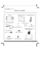
What’s in the Box? homebase Wall Mount Bracket (1) AC to DC Power Adapter (1) Angle Mount Bracket (2) Post-It ® Note Pad (1) Button Magnet (2) Adhesive Foam Pad (2) Wire Management System (3) (Black, White, Clear) Dry Erase Marker (1) Plastic Wall Anchor (2) Flat-Head Self-Tapping Screw (2) 6 Double-Sided Tape (1) Mounting Hole Template (1) DPF710K
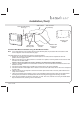
Installation homebase Bracket Mounting Holes Wire Post(s) Power Adapter Wire Notch Refrigerator Door Front Surface DC Input Connector Refrigerator Door Seal DC Power Wire 1 inch Power Adapter Wire Notches Wire Cover homebase Adhesive Foam Pads Wire Cover Wall Mount Bracket See Step 9 Caution Below homebase Refrigerator Installation 1. Remove the protective backing from one side only of the two adhesive pads and position them on the back of the wall mount bracket as shown. 2.
Installation (Cont) Angle Bracket Mounting Holes homebase Unit DC Input Connector Wire Post(s) Power Adapter Wire Notches Bracket Upper Mounting Tabs Bracket Lower Mounting Tabs Angle Mount Brackets homebase Countertop Installation 1. Find a suitable location on the countertop adjacent to an AC wall outlet. 2. Connect the power adapter plug to the DC input connector at the rear of the homebase. 3. Choose the direction of the adapter wire in reference to the AC wall outlet.
Installation (Cont) Flat-Head Self-Tapping Screw (2) Wall Surface Drill 1/4" Hole (2 Places) Mounting Hole Template Wall Bracket Mounting Tabs Wall Mount Bracket Plastic Wall Anchor (2) if Needed homebase Wall Mount Installation Using the Wall Mount Bracket Note: If the wall bracket is to be mounted using the foam adhesive pads, the procedure will be the same as that for the refrigerator mount as described on page 7. If the wall bracket is to be mounted using screws, proceed as follows: 1.
Installation (Cont) Plastic Wall Anchor (2) if Needed Drill 1/4” Hole (2 Places) Angle Mount Bracket Mounting Tabs Wall Surface Flat-Head Self-Tapping Screw (2) Angle Mount Bracket (2) Mounting Hole Template homebase Wall Mount Installation Using the Angle Mount Brackets Note: Foam adhesive pads are not recommended when mounting the angle mount brackets to a wall surface. Mount the brackets to the wall surface as follows: 1.
Installation (Cont) Internal Battery Activation and/or Replacement A type CR2032 battery is installed in a compartment behind the front panel of the homebase. If the unit is being used for the first time, the battery must be activated. A plastic insulator prevents contact with the battery terminals. This insulator must be removed for the calendar/ clock backup functions to operate. To remove the insulator, simply pull out the plastic tab extending from the right side of the unit below the marker pen.
Controls, Indicators and Connectors 1 5 2 6 3 7 4 8 9 13 10 14 11 12 15 1. Power On/Off Switch 2. USB Connector 3. SD/MMC/MS/XD Connector 4. CF Connector 5. Up ( ) Navigation Button 6. OK / MENU Button 7. Down ( ) Navigation Button 8. MEMO Button 9. LCD Display 10. LED Indicator 11. Memo Writing Surface 12. Microphone 13. Speakers 14. - Volume + Control 15.
Accessory Placement Note Pad Storage Receptacle Post-It® Note Pad Dry Erase Marker homebase DPF710K Marker Storage Receptacle 13
Operating the homebase Preliminary Connections Prior to initial operation, connection must be made to the power source and the tab (“REMOVE THIS TAB”) on the right side of the unit must be removed to enable backup battery operation. Connecting the Power. Power to the homebase is provided by the AC-to-DC wall adapter which delivers +9VDC to the DC input connector at the rear of the unit.
Power On/Main Menu Preliminary Checks With the homebase properly installed, perform the following precautionary checks prior to power application: 1. 2. 3. Make sure the power switch on the upper left side of the unit is in the Off (down) position. Check the wall adapter and power cable for cuts, nicks, kinks, etc. Plug the adapter plug into a wall outlet. Power On/Main Menu 1. 2. 3. Place the power switch in the On (up) position.
Memo Feature Highlight MEMO in the main menu using the up/down buttons ( / ) exit -----and press OK ----- memo calendar timer photo highlight record using the down button ( ) and press OK -------Record is active------ settings exit record play / erase Or press the memo button When record is finished --Press the down button ( ) to highlight desired function, e.g., review, keep / exit, record again, cancel erase all recording...
Calendar Memos 1. Recording Calendar Memos Highlight calendar in the main menu using the up/down buttons ( / ) -----and press OK----- exit memo memo calendar Note: Use the up/down buttons ( / ) to scroll from day to day and pressing and holding up/down buttons ( / ) for 2 seconds advances to the next month.
Calendar Memos (Cont) 2. Reviewing Calendar Memos Highlight calendar in the main menu using the up/down buttons ( / ) Note: Use the up/down buttons ( / ) to scroll from day to day and pressing and holding up/down buttons ( / ) for 2 seconds advances to the next month.
Countdown Timer Highlight timer in the main menu using the up/down buttons ( / ) exit ----and press OK---- memo calendar timer photo setting countdown timer 00:10:00 h m s A split screen display appears with the countdown timer on the left and a slide picture on the right. If the slide show is in progress when the timer function is selected, the slide show stops at the current picture and appears in the timer display background. a.
Photo Menu Highlight photo in the main menu using the up/down buttons ( / ) exit ----and press OK---- memo memo calendar timer Highlight external media using the up/down buttons ( / ) and press OK photo settings exit external media photo library slide show Highlight photo library using the up/down buttons ( / ) and press OK to access photos stored in the library file. If none exists, this feature is not supported.
Photo Library Menu Full screen picture appears with slide show menu overlay with back highlighted Slide show thumbnail display appears when input device connected Use the up/down buttons ( / ) to highlight and select desired picture Press OK 1 / 62 exit back single slide display delete next rotate Select back and press OK to return to thumbnail screen; select exit and press OK to display full screen slide show 1. Single Slide Display - 2.
External Media Menu Full screen picture appears with slide show menu overlay with back highlighted Slide show thumbnail display appears when input device connected Use the up/down buttons ( / ) to highlight and select desired picture exit back copy next Press OK copy all Select back and press OK to return to thumbnail screen; select exit and press OK to display full screen slide show Use the up/down buttons ( / ) to highlight the next option Use the up/down buttons ( / ) to highlight the copy option
Settings 1. General Setup - Photo Mode Selection Highlight settings in the main menu using the up/down buttons ( / ) exit memo memo calendar timer photo settings and press OK Highlight general setup using the up/down buttons ( / ) exit general setup time / date setup alarm clock display and press OK 1. Photo Mode - Select between normal mode and wide screen. 2. Activation Time - Set a time for the unit’s display to turn off and turn on to conserve energy.
Settings (Cont) 2. General Setup - Time / Date Setting a. In the Settings menu, highlight time / date setup using the up/down buttons ( / ) and press OK. b. The time / date display appears with the hour digit(s) flashing. c. Use the up/down buttons ( / ) to set the hour and press OK. d. The minutes digits are now flashing; use the up/down buttons ( / ) to set the minutes and press OK. e. The AM/PM indication now flashes; use the up/down buttons ( / ) to set the AM or PM indication and press OK. f.
Settings (Cont) 3. General Setup - Alarm Setting In the Settings menu, highlight alarm using the up/down buttons ( / ) and press OK To program the alarm time, use the up/down buttons ( / ) to highlight alarm set and press OK exit alarm on/off alarm set Clock is displayed in the center of the screen (below), along the bottom edge of the screen, or in the split screen configuration exit alarm on/off alarm set Highlight alarm on/ off using the up/down buttons ( / ) and press OK Wednesday - Dec.
Settings (Cont) 4.
Technical Data Specifications • • • • • • • • • • • • • • • Digital Picture Frame 7” LCD Aspect Ratio 16:9 Resolution: 480 x 234 pixels Internal Flash Memory 512 MByte USB Connector Provides interface for external USB memory device SD/MMC/MS/xD Card Slot Provides interface for memory device CF Connector Provides interface for CF memory device Date/Time Digital Calendar and Clock Feature Voice Messages Internal microphone for digital audio recording Audio Output Internal speakers (2) wit
Warranty 90 DAY LIMITED WARRANTY Applies to Audiovox Video Products AUDIOVOX ELECTRONICS CORP. (the Company) warrants to the original retail purchaser of this product that should this product or any part thereof, under normal use and conditions, be proven defective in material or workmanship within ninety (90) days from the date of original purchase, such defect(s) will be repaired or replaced with reconditioned product (at the Company's option) without charge for parts and repair labor.
Notes DPF710K 29
Notes 30 DPF710K
Notes DPF710K 31
Audiovox Electronics Corp.