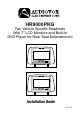
® HR9000PKG Two Vehicle Specific Headrests With 7" LCD Monitors and Built-In DVD Player for Rear Seat Entertainment Installation Guide 128-7631B
IMPORTANT An LCD panel and/or video monitor may be installed in a motor vehicle and visible to the driver if the LCD panel or video monitor is used for vehicle information, system control, rear or side observation or navigation. If the LCD panel or video monitor is used for television reception, video or DVD play, the LCD panel or video monitor must be installed so that these features will only function when the vehicle is in ‘park’ or when the vehicle’s parking brake is applied.
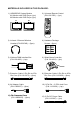
MATERIALS INCLUDED IN THIS PACKAGE: 1) HR9000PKG System Monitor M1 Monitor with DVD Player (1pc) M2 Monitor with DVD Player (1pc) M1 2) Universal Remote Control (P/N 136-3785) – (1pc) M2 3) Infrared 2 Channel Wireless Headset (P/N IR2CHS) – (2pcs) 4) Hardware Package Screws – (8pcs) 5) Wireless FMM Interface Box (P/N 136-4185) – (1pc) 6) Wired Game Controller (P/N 136-4212) – (1pc) 7) Extension Cable, 8 Pin Din to 8 Pin Din Conn (P/N 112-3673) – (2pcs) 8) Extension Cable, 8 Pin Din to 8 Pin Din Conn
HR9000PKG SYSTEM OVERVIEW 1) The HR9000PKG is a versatile audio / video system with built-in DVD which includes two monitors, that can accept an Audio / Video input and independent AUX input. A separate audio output is provided for connecting the FM Modulator to the vehicle's radio. 2) The M1 Monitor is comprised of a 7" TFT LCD monitor with built-in DVD player that allows the user to select from DVD, A/V, AUX/GAME sources.
7) The M1 and M2 Monitor will accept an audio / video input through the 1/8” jack and the Game Controller Game Port located on the front of the unit. The audio / video device could be a video game system, video camera, or other input device. Note: If the Game Controller is plugged in and an AUX source is plugged in to the AUX input, the AUX input will override the Game Controller. To use the Game Controller, unplug the AUX input.
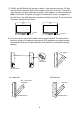
VEHICLE PREPARATION: 1) Read the manuals and get familiar with the electrical requirements and connections. 2) Prepare the vehicle by removing any interior trim necessary to gain access to the vehicle's wiring as well as all areas where interconnecting wire harnesses will be located. (Refer to the Installation Procedure).
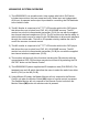
) Connect all the components together (electrically) and verify proper operation of all the system functions. A) The headrest DIN cables and the FMM inter-connect box DIN cables are color coded. Connect each headrest cable to the correct color cable on the FMM inter-connect box. In some vehicles it will be necessary to use the supplied DIN extension cables to reach from under one seat to the other seat. The DIN extension cables can be used for either the M1 or M2 monitors.
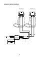
HR9000PKG WIRING DIAGRAM M1 Monitor M2 Monitor Master Monitor Satellite Monitor M1A M1B M2A 2 PIN DC POWER CABLE DC IN AV Input AV Output INTERFACE BOX FM ANTENNA Optional DIN Extension Cables Antenna for wireless FM MOD See antenna note below 6 M2B
For Customer Service Visit Our Website At WWW.audiovox.com Product Information, Photos, FAQ’s Owner’s Manuals © 2006 Audiovox Electronics Corp.